
Battery energy storage projects concentrate inverters, transformers, medium-voltage switchgear, protection devices, and auxiliary systems into compact blocks. The cable joint between those blocks may look like a small part of the installation, but it controls whether the equipment bushing, cable, current path, screen, and available space work as one system. At YIEOU, we manufacture medium-voltage cable accessories for these interfaces. When we select a Separable Connector for a battery energy storage system (BESS) skid, we begin with the actual equipment interface and cable—not with a familiar Separable Connector shape. This application-led method helps avoid a Separable Connector that fits the conductor but does not fit the bushing, the insulation diameter, the screened system, or the installed cable route.
Quick Answer
Select the Separable Connector for a BESS MV skid by confirming five linked conditions: the bushing interface specified on the transformer or switchgear, the system voltage and continuous current, the cable conductor and insulation dimensions, the number and direction of cable circuits, and the usable compartment space after the cable is bent and supported. A 630A European-style front connector, a 600A-class deadbreak T-body, and a 200A loadbreak elbow belong to different interface systems. Similar current labels or similar-looking bodies do not make them interchangeable.
For many 12/24kV BESS skids with standardized C-type equipment bushings, our screened 630A European-style front and rear connector arrangements provide a compact detachable cable interface. The rear connector is useful only when the equipment, front connector, stud system, electrical design, and compartment geometry support the intended second connection. The correct Separable Connector remains part of a complete assembly: bushing, connector body, conductor contact, cable adapter, screen connection, grounding path, mechanical support, and installation procedure all have to agree.
Read the BESS MV Connection Path Before Choosing Hardware
A BESS block can connect a step-up transformer to an RMU, metal-enclosed switchgear, a collector feeder, or a station bus. The same project may contain several cable interfaces that perform different jobs. One Separable Connector may terminate an inverter-transformer skid feeder; another may enter a ring unit; a third may form the outgoing collector circuit. We therefore read the single-line diagram and the equipment interface schedule together before we define the Separable Connector.
The one-line diagram tells us where power flows, but it does not show everything that affects the cable accessory. We also check whether the cable enters from below or from the side, whether the connection compartment is front-access or rear-access, whether the transformer and switchgear use the same bushing family, and whether a second cable or test arrangement is planned. In a modular storage plant, identical-looking skids can even contain different transformer or RMU variants. The Separable Connector decision must follow the installed interface at each location.
This is also where our manufacturer perspective matters. We do not treat “BESS cable” as a product specification. We translate the application into an interface definition. A useful definition identifies the equipment bushing, rated voltage, continuous current, conductor material and size, cable insulation material, insulation diameter, screen construction, entry direction, and available mounting depth. Once those items are known, the suitable Separable Connector family becomes much clearer.
| BESS MV connection point | Main interface question | Practical connector consequence |
|---|---|---|
| Step-up transformer cable box | Which bushing interface is installed, and how much depth remains after the cable is dressed? | Select the matching interface family and verify the complete connector-plus-cable envelope. |
| RMU or switchgear feeder way | Is the bushing C-type, 600A deadbreak, 200A loadbreak, or another defined interface? | Do not cross-select between systems; match the equipment interface first. |
| Ring or collector connection | Is one cable sufficient, or is an approved front-and-rear arrangement required? | Confirm the stud stack, current path, support, and compartment geometry before adding a rear connector. |
| Spare or future circuit position | Is the position energized, isolated, or reserved under the equipment design? | Use the equipment maker’s specified insulating and protective arrangement; do not leave an interface improvised. |
The table is a starting point, not a replacement for the equipment drawing. We manufacture the Separable Connector around a defined interface, while the final assembly must also respect the transformer or switchgear instructions.
Match the Interface Family Before the Current Rating
The interface family is the first hard boundary. Our QJT 12/24-630A European-style front connector is designed for standard C-type bushings used on equipment such as switchgear, RMUs, transformers, and cable branch boxes. The product is rated up to 24kV and 630A and is designed as a fully screened, insulated detachable termination. In a BESS skid that actually uses this bushing interface, a Separable Connector from the European 630A range can provide the required equipment-to-cable transition.
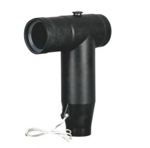
The rating alone does not define compatibility. A 600A-class American deadbreak T-body uses a different equipment interface and connection system. Our JY TT-600 is a 15/24kV, 600A-class deadbreak connector for matching apparatus interfaces; “deadbreak” means the circuit must be de-energized and handled under the specified safe procedure. It must never be described or used as a load-interrupting elbow. A 200A loadbreak system is another distinct family with its own bushing insert, elbow, contact, and operating limits.
That separation is especially important in mixed-source BESS packages. A project may combine a transformer supplied by one manufacturer and switchgear supplied by another. The drawings may show similar T-shaped cable terminations at both ends, yet the interfaces can be different. We mark each connection point by interface family, not by silhouette. When a 600A-class deadbreak interface is specified, the matching Separable Connector must be selected within that system rather than substituted by a European 630A body.
Standards help define interfaces, but a standard reference by itself does not complete the selection. Our European front connector page refers to DIN 47636, EN 50180/50181, and IEC 60502-4. We still verify the exact bushing designation and equipment dimensions. The safest technical language is specific: the Separable Connector is compatible with a defined interface when all mating dimensions and ratings agree. “Standard 24kV connector” is too vague for production or installation.
Match the Separable Connector to the Actual Cable
After the bushing family is fixed, we select the cable-side components. Conductor cross-section is necessary, but it is not enough. Two 240mm² cables can have different insulation diameters, conductor constructions, screen systems, and oversheath dimensions. Those differences affect the conductor contact, cable adapter, sealing zone, stress-control geometry, and the way the cable enters the Separable Connector body.
For the QJT 12/24-630A range, our published selection window covers copper or aluminum conductors, with conductor-size ranges that depend on voltage class. The actual kit selection uses the cable insulation diameter within the product’s defined adapter range. We therefore use the cable manufacturer’s dimensional data and confirm it against the supplied cable, particularly when the project changes cable brand or construction after the skid layout was frozen.
A correct Separable Connector selection normally resolves the following cable details together:
- conductor material and construction, because the contact and installation method must suit copper or aluminum and the specified conductor form;
- conductor cross-section, because the compression or mechanical contact has a defined range;
- insulation material and nominal thickness, because the prepared insulation surface interfaces with the stress-control and adapter components;
- measured or controlled insulation diameter, because it determines the correct cable adapter size;
- metallic screen type and grounding arrangement, because wire screen, tape screen, and other constructions are prepared differently;
- oversheath diameter and cable-entry sealing, because the finished lower section must remain within its dimensional and environmental limits.
We avoid selecting the Separable Connector from a cable designation alone when the relevant dimensions are missing. We also avoid “making it fit” by removing extra insulation, stretching an unsuitable adapter, or changing the conductor contact. Those actions alter the designed electrical and mechanical interfaces. Our role as the manufacturer is to keep the complete connector kit inside its qualified range and to make the selection boundary clear before installation.
Cable preparation quality then determines whether the selected components can perform as designed. The semiconductive layer transition should be smooth, the insulation surface clean and undamaged, the cut lengths controlled, and the conductor contact installed with the specified tooling and sequence. A Separable Connector selected correctly on paper can still fail if the cable is scored, contaminated, or cut to an improvised dimension. For that reason, we link application selection with the actual installation method rather than treating them as separate subjects.
Use Front and Rear Connections Only When the System Supports Them
A compact BESS skid may need a ring connection, two cable circuits on one equipment way, or a future expansion path. A front-and-rear Separable Connector arrangement can be useful in those cases, but it is not a universal way to add another feeder. Our HJT 12/24-630A European-style rear connector is designed to work with the corresponding front connector system on suitable 24kV European distribution equipment. It is a screened detachable rear connection for the intended stud and interface arrangement.
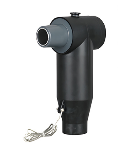
Before we specify a rear Separable Connector, we confirm that the equipment bushing, front connector, connecting stud, current path, and rear interface are all designed for the assembled stack. The continuous current of the connection is not created by adding connector ratings together. The current path remains limited by the rated components and by the equipment design. The rear body also adds depth and changes the cable exit position, so the cabinet must accommodate the complete assembly without forcing either cable.
The electrical function must be equally clear. A second connection may serve a ring circuit, a parallel path permitted by the system design, or a defined outgoing cable. It should not be added merely because a rear socket appears available. Protection coordination, conductor loading, switching sequence, and equipment ratings remain system-level responsibilities. The Separable Connector provides the cable interface; it does not decide how the two circuits should operate.
We also plan the installation sequence. In a tight compartment, the rear cable may need to be prepared and positioned before the front cable is fully dressed. Earthing leads, screen wires, cable cleats, and phase spacing all need accessible routes. A technically compatible stack that cannot be installed without twisting the cable or blocking the grounding connection is not a workable BESS skid solution.
Fit the Complete Assembly Inside the Skid Compartment
Compact equipment makes mechanical layout part of electrical reliability. Separable Connector drawings often show the molded body, while the installed envelope also includes the bushing projection, stud, conductor contact, cable adapter, cable bend, screen-earth lead, cleat, and the space needed for installation tools. We check that entire envelope when we propose a Separable Connector for a storage skid.
The cable should enter the connector close to its natural axis. Pulling a stiff medium-voltage cable sideways to reach the bushing can apply continuous force to the adapter and contact system. An immediate sharp bend below the connector can also crowd adjacent phases and make the screen connection difficult to inspect. The cable bending radius from the cable manufacturer, the vertical support position, and the distance to the compartment floor should be coordinated before the skid structure is finalized.
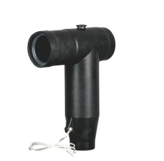
Our JY JB-15/630 European front connector illustrates the compact screened T-body form used for a matching 15kV, 630A interface. Its shape is useful in restricted equipment spaces only when the cable can still be prepared, inserted, supported, and grounded without distortion. The product body should not be used as a cable support. We place cleats or supports so the cable weight and short-circuit mechanical forces are carried by the intended structure.
Phase-to-phase access also matters. Installers need room to clean the interfaces, apply the specified lubricant where required, tighten the connection with controlled tools, connect grounding leads, and fit any test-point cap or protective component. We prefer a layout that lets each phase be installed and inspected directly. Hiding one phase behind another may reduce enclosure width on a drawing, but it can increase the risk of incomplete seating or damaged screen leads during field work.
For skid builders, a simple three-dimensional clearance check is often more useful than a flat cable schedule. It should show the installed Separable Connector, the real cable outside diameter, minimum bend path, cleat position, door and barrier movement, and the tool approach. This check is particularly valuable when the same enclosure will accept more than one cable cross-section or supplier.
Keep Environmental Conditions Inside the Product Boundary
BESS equipment may be installed outdoors, inside a ventilated container, or in a prefabricated electrical room. These settings can expose the cable compartment to condensation, dust, temperature cycles, coastal contamination, or occasional water ingress. A screened connector can support a compact and controlled interface, but its environmental performance depends on the complete installed assembly and the enclosure conditions.
Our European front and rear connector products are designed for indoor and outdoor medium-voltage applications within their stated limits. The molded insulation and conductive outer screen are not a substitute for correct sealing, grounding, cable preparation, or enclosure design. The outer screen must be connected as specified so that the surface remains at a controlled potential. Unconnected or damaged screen leads should never be treated as a cosmetic issue.
Condensation deserves particular attention in storage skids because equipment cycles and auxiliary cooling can create changing internal temperatures. We keep water paths away from cable entries, preserve drainage and anti-condensation measures, and avoid routing earth braids where they can wick moisture into a prepared cable end. If the compartment is expected to be submerged or exposed beyond the connector’s stated environmental rating, we stop and define a suitable system rather than assuming every screened Separable Connector is automatically submersible.
Temperature affects both current-carrying equipment and cable layout. The connector current rating is one part of the thermal chain; the bushing, conductor contact, cable, enclosure ventilation, grouping, ambient temperature, and duty profile also matter. A BESS plant can have long charge or discharge periods, so repeated high-current operation should be considered at the system level. We do not increase a connector’s usable current because the duty is described as intermittent without an approved engineering basis.
At one unobtrusive point in the technical file, it is useful to remember that a Connector is an interface between parts of a circuit. In the MV skid, that interface remains dependent on the ratings and condition of everything on both sides.
Verify the Whole Interface Before Energization
Final verification should confirm identity, assembly, grounding, support, and electrical condition. It is not enough to see that a black T-body is present on each phase. We compare the installed markings and kit components with the approved interface definition, then inspect the cable preparation and seating against the installation instructions.
| Verification point | What we check on the BESS skid | Why it matters |
|---|---|---|
| Equipment interface | Bushing family, voltage class, current class, stud and mating dimensions | Prevents a visually similar but incompatible Separable Connector from being installed. |
| Cable match | Conductor material and size, insulation diameter, adapter, screen and oversheath | Keeps the contact, stress-control and sealing components within their designed ranges. |
| Mechanical installation | Full seating, controlled tightening, cable alignment, bending radius and cleat support | Avoids loose contact, distorted bodies, and continuous mechanical load on the bushing. |
| Screen and earth path | Connector screen lead, cable screen treatment and equipment earth connection | Maintains the intended screened interface and fault-current path. |
| Front/rear stack | Approved components, correct sequence, adequate depth and independent cable support | Confirms that an expanded connection is electrically and mechanically complete. |
| Test and condition | Clean interfaces, intact test-point components where fitted, project-specified electrical tests | Establishes a documented baseline before the circuit is energized. |
The test program belongs to the project and equipment requirements. Depending on the installation, it may include insulation checks, phase identification, screen continuity, sheath testing, contact-resistance assessment, or other approved tests. A capacitive test point, where supplied as part of a particular Separable Connector, is a voltage-presence indication feature used with the specified device and procedure; it is not proof by itself that the circuit is safe to touch.
We also check that switching language matches the product duty. A 600A deadbreak connector is operated only after isolation and verification under the approved procedure. A 630A European screened connector is not treated as a handheld loadbreak device. Any actual switching function belongs to the RMU, switchgear, or another rated apparatus. Keeping these functions separate prevents the cable accessory from being asked to perform a task it was never designed to perform.
For repeat skid production, the interface definition can be standardized without losing technical control. We maintain a connector selection record tied to the equipment bushing and cable dimensions, and we verify any component change against that definition. This is an engineering configuration check, not paperwork for its own sake. It ensures that a revised cable or equipment variant does not silently invalidate the original Separable Connector selection.
Conclusion
The right Separable Connector for a battery energy storage system MV skid is selected from the connection outward: equipment bushing first, then voltage and current, cable dimensions and screen construction, circuit arrangement, installed space, environment, grounding, and verification. Starting with conductor cross-section or a familiar T-body shape leaves critical interfaces unresolved.
At YIEOU, we manufacture European-style and American-style medium-voltage cable accessories for defined equipment interfaces. For a BESS project, we use that product range to build a coherent cable-to-equipment connection, not to force different systems into a common label. When the bushing, connector kit, cable, compartment, and operating duty are matched as one assembly, the storage skid becomes easier to install, inspect, and maintain throughout its service life.
Frequently Asked Questions
Which detail should be confirmed first for a BESS Separable Connector?
Confirm the equipment bushing interface first. The bushing family determines the mating geometry and connector system. Voltage, current, cable size, and compartment layout are then checked within that family. A cable cross-section alone cannot identify the correct Separable Connector.
Can a 630A European connector replace a 600A deadbreak T-body?
No. They belong to different interface systems. Even if both are used on 15/24kV equipment and their current ratings look close, the bushing, stud, body geometry, contact system, and accessories are not interchangeable. We select each product to the actual apparatus interface.
Is a rear connector always suitable for adding a second BESS cable?
No. A rear Separable Connector is suitable only when the matching front connector, equipment bushing, stud stack, electrical design, current path, and compartment clearances support that arrangement. The second cable also needs its own route, bend radius, grounding, and mechanical support.
Why is cable insulation diameter needed when conductor size is known?
The cable adapter and stress-control interface fit over the insulation, not over the conductor. Cables with the same conductor cross-section can have different insulation diameters. We use the diameter range specified for the connector kit so the adapter and molded body work within their designed geometry.
Does the screened connector body support the cable weight?
No. The connector body and equipment bushing should not carry the cable as a structural support. The cable needs properly located cleats or supports so its weight, bend reaction, and possible short-circuit forces are transferred to the skid structure.
Can a deadbreak Separable Connector interrupt BESS load current?
No. A deadbreak connector must be de-energized before it is separated, following the approved isolation, verification, and grounding procedure. Load interruption belongs to rated switchgear or a specifically rated loadbreak system, not to a deadbreak connector.
What should be checked before the BESS MV circuit is energized?
Verify the bushing and connector identity, cable adapter and contact selection, complete seating, specified tightening, screen and earth connections, cable support, phase identification, cleanliness, and the project-required electrical tests. We also confirm that all caps, test-point components, barriers, and compartment parts are restored to their intended condition.