
High-power electric vehicle charging is often discussed from the charger outward: connector power, vehicle dwell time, software, and user flow. Yet once a site grows into a multi-megawatt charging hub, the medium-voltage connection behind the chargers becomes just as important. The cable interface between the ring main unit, switchgear, transformer, and site feeder must carry the intended current, fit the installed cable, remain sealed in a compact enclosure, and still be serviceable after the station is energized.
As a medium-voltage cable accessory manufacturer, we see the same practical issue across charging depots, highway fast-charging sites, and fleet yards. A Separable Connector cannot be chosen from voltage and conductor size alone. The equipment bushing interface, operating method, cable construction, screen continuity, mechanical route, and environmental exposure have to agree as one installed system. When those conditions are resolved early, the connector becomes a controlled part of the charging hub rather than a late-stage fit problem.
Quick Answer
For a high-power EV charging hub, select the Separable Connector from the actual equipment bushing first, then confirm system voltage, continuous and fault current duties, cable insulation diameter, conductor material and size, screen construction, installation space, cable bend, and whether the circuit is deadbreak or loadbreak. A 600A American-style deadbreak interface, a 630A European-style interface, and a 200A loadbreak interface are different systems even when they appear in equipment serving the same charging site. They are not interchangeable by current rating or by cable cross-section.
In our manufacturing work, we treat the bushing, connector body, conductive path, stress-control geometry, cable adapter, screen connection, grounding lead, and protective closure as one interface. This approach is especially important in charging infrastructure because the electrical room is often compact, the load can remain high for long periods, and future feeder additions may already be planned. The correct Separable Connector must fit the equipment that exists today without creating a false assumption about how tomorrow’s expansion will be connected.
Why a Charging Hub Places Real Demands on the MV Cable Interface
A small charging site may be supplied from an existing low-voltage service, but a large depot or public fast-charging hub can concentrate enough demand to justify a dedicated medium-voltage supply and local transformation. Several chargers may operate at the same time, producing long periods of meaningful transformer and feeder loading rather than an occasional short peak. This does not mean the cable connector should be selected by charger nameplate totals. It means the installed medium-voltage path must be considered as a continuous electrical and thermal system.
The Separable Connector sits at a physical transition. On one side is a standardized equipment bushing fixed in switchgear, a ring main unit, a compact substation, or a transformer. On the other is a prepared polymeric cable whose conductor, insulation, semiconductive screens, metallic screen, and oversheath must terminate in a controlled geometry. The connector has to maintain contact pressure and electrical continuity while the stress-control region manages the field at the cutback of the cable screen. Its external semiconductive layer must also remain correctly bonded to ground so that the accessible surface behaves as intended.
Charging hubs add practical pressure to this transition. Equipment is often arranged in prefabricated rooms or narrow outdoor enclosures to preserve vehicle circulation, while cable trenches may enter from below with little spare length. Where the route is fixed, even a technically compatible connector can be difficult to install without forcing the cable or loading the equipment bushing.
This is why we manufacture and apply the Separable Connector as part of the physical interface, not as an isolated rubber component. The connector must suit the charging site’s real enclosure, real cable route, and real operating boundary. If those conditions are not examined together, a selection that looks correct on a schedule can still be wrong at the equipment door.

The Equipment Bushing Decides the Connector System
The first decisive question is not the cable cross-section. It is the interface molded or mounted on the equipment. A charging hub design may include equipment from different manufacturers, and two units with similar voltage and current ratings can still present different bushing profiles. The Separable Connector must match the dimensional and electrical interface of that bushing. An apparently close fit is not an acceptable fit because the contact system, sealing surfaces, insulation overlap, and assembly force depend on the defined geometry.
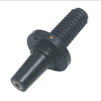
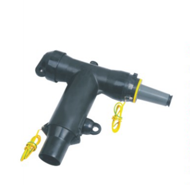
Our 15kV/24kV 600A American-style deadbreak products illustrate this point. A T-shaped front connection is intended to mate with the corresponding 600A-class equipment interface and associated deadbreak components. We manufacture the rubber body with an internal conductive path, insulation layer, stress-control region, external screen, and grounding provision arranged for that interface. The interface identity comes before any adjustment for the cable itself.
The term deadbreak is also an operating boundary. A deadbreak Separable Connector is disconnected only after the circuit has been de-energized, isolated, tested, and grounded under the site’s approved procedure. It is not a device for interrupting charging-hub load current. A 200A loadbreak elbow belongs to another interface family designed around a different operating function and geometry. A 630A European-style connector is another distinct system again. Calling all three “medium-voltage connectors” does not make their bushings, accessories, or operating methods compatible.
This distinction matters when a charging hub contains mixed equipment. The incoming ring main unit may use one interface while a transformer or branch cabinet uses another. The correct response is to identify each equipment termination individually, not to force a single connector description across the entire site. A clear bushing drawing or confirmed interface designation is more useful than a general statement such as “600A connector required.” It establishes the system that the Separable Connector must actually complete.
Cable Construction Changes the Installed Fit
After the equipment interface is known, the cable determines the connector’s cable-side configuration. Conductor cross-section is important because it affects the crimp or shear-bolt connection, but it is only one part of the fit. Two cables with the same nominal conductor area can have different conductor diameters, insulation thicknesses, insulation diameters, semiconductive screen constructions, metallic screens, and oversheath dimensions. These differences affect the terminal, cable adapter, sealing range, preparation dimensions, and the stress-control region of the Separable Connector.
For charging hubs, we therefore work from the actual cable data rather than a shorthand cable label. The conductor material determines whether the conductive connection should be prepared for copper or aluminum. The measured or manufacturer-declared diameter over insulation determines the adapter range. The metallic screen may use copper wires, tape, or a combined construction, and the grounding arrangement must preserve screen continuity without creating sharp bends or unsecured strands. If water-blocking layers or special oversheaths are present, the preparation method must account for them without contaminating the insulation surface.
Cable preparation quality is inseparable from product selection. The insulation cut must be smooth, the semiconductive screen transition must be free of deep scoring or steps, and the prepared surface must remain clean and dry. A correctly specified Separable Connector cannot compensate for damaged insulation or an incorrectly positioned screen cutback.
We also consider the installed thermal path. A high-power charging site can hold substantial load for extended periods, so the conductor connection, contact resistance, cable rating, enclosure temperature, and surrounding soil or duct conditions all influence temperature rise. It is not rigorous to claim that a connector is suitable only because its current class is higher than the calculated site load. The complete circuit needs an appropriate continuous-current evaluation, including expected diversity and the thermal conditions around the actual installation.
Compact Charging Sites Need a Natural Cable Route
Medium-voltage compartments are often shown as clean rectangles on a single-line diagram. In the field, the Separable Connector occupies three-dimensional space with a cable that resists bending. The body needs room to align with the bushing, the cable needs a gradual route into the termination, and the installer needs enough access to prepare, push, secure, and ground the assembly. These requirements are particularly important in compact charging hubs where electrical equipment is placed along a boundary wall or inside a prefabricated power room.
A cable should not be used as a lever to bring the Separable Connector onto the bushing. Side load can disturb alignment, place mechanical stress on the equipment interface, and make full seating difficult to verify. The minimum bend radius also applies during installation, not only after the enclosure door is closed. If the trench entry is too close to the bushing centerline, the cable may need to reverse direction sharply. If the cable is cut too short, there may be no safe way to remake the termination after a preparation error.
In our application reviews, we consider bushing orientation, phase spacing, the distance from the trench opening, and the direction in which the cable naturally approaches the equipment. The dimensions of the Separable Connector matter, but so does access to the test point, grounding lead, and protective closure. A compact body does not solve a poor cable route.
This is an area where early dimensional coordination saves real work. A charging station layout may still have flexibility before the enclosure base, cable trench, and transformer position are fixed. Moving a cable entry or changing bushing orientation at that stage can produce a more reliable termination than trying to force the final cable into an unsuitable geometry. The goal is not simply to make the parts fit once. It is to leave the Separable Connector seated without permanent mechanical strain throughout service.
Expansion Must Stay Within One Coherent Interface System
Charging sites are frequently built with an expectation of more dispensers, higher charger utilization, or additional transformer capacity. That expectation should influence space, feeder, and equipment planning, but it should not lead to improvised stacking of detachable components. A Separable Connector system can support defined branching or connection arrangements only when the bushing, front body, rear body, connecting hardware, insulating closure, and cable-side components are designed to operate together.
For a 600A American-style deadbreak arrangement, a T-shaped body and its matching components can create a compact screened connection at the equipment interface. In our range, the JY QJT-600 front body and the JY TIIT-600 deadbreak assembly demonstrate how connected components share the same functional geometry. We mention them here because they show the principle: expansion is achieved through a verified interface path, not by adding a component that happens to have the same nominal current printed on its page.
The future circuit also needs its own protection, cable rating, switching arrangement, and equipment duty. The Separable Connector does not create feeder capacity, change transformer capability, or replace a switching device. An unused interface must be closed with the correct insulated and grounded protective component for that system. Leaving a branch position loosely defined until construction makes it easier to mix interface families or overlook the physical depth of the completed assembly.
Where a charging hub may expand, we recommend preserving both electrical clarity and physical access. The present installation should be complete and safe in its current state, while the enclosure and cable route should allow the planned future assembly to be installed under a controlled outage. That is a more dependable basis for expansion than treating every detachable interface as universally modular.
Outdoor Reliability Depends on the Complete Screen and Seal
Many EV charging hubs place the transformer, ring main unit, or compact substation outdoors. Even when the Separable Connector is inside a metal compartment, it may experience humidity, daily temperature cycling, condensation, dust, road spray, and pollutants carried in by ventilation or maintenance access. A screened and sealed Separable Connector is valuable in these conditions, but only when every interface is clean, fully seated, correctly grounded, and closed with the matching component.
The external semiconductive layer of a screened connector is not decorative. When it is correctly connected to ground, it helps maintain a controlled surface potential and continues the cable screen function across the termination. Grounding leads must be secure and routed so that they are not strained, trapped by the door, or left vulnerable to corrosion. The metallic cable screen and equipment grounding system must be treated as part of the installation, not as an afterthought once the connector body is in place.
Sealing also depends on preparation. Dirt on the bushing interface, damage to a sealing surface, incorrect lubricant, or incomplete seating can undermine the intended environmental performance. Moisture does not need a dramatic flood path to become a problem; repeated condensation and contamination at an interface can gradually reduce confidence in insulation condition. For outdoor charging infrastructure, drainage and compartment design still matter even when a Separable Connector is described as sealed or submersible.
The broader idea of a Connector is a removable electrical interface. At medium voltage, removability must be supported by field control, insulation coordination, screening, sealing, and a defined operating procedure. That is why visual similarity is not enough to establish compatibility. We verify the full assembly because the electrical and environmental functions are shared across its parts.
Maintenance Access Starts With the Original Layout
A charging hub is expected to remain available, and an outage can affect many charging positions at once. The Separable Connector can support testing, isolation, or replacement, but only if the equipment was laid out so qualified personnel can reach it safely. A termination hidden behind rigid cable bends or crowded by auxiliary wiring may be detachable in theory and inaccessible in practice.
The Separable Connector’s capacitive test point, where provided, is an indication and test feature that must be used with the correct device and procedure. It is not a substitute for approved absence-of-voltage verification. Similarly, a deadbreak assembly must not be separated to diagnose a live circuit. The circuit has to be switched off, isolated, tested, discharged, and grounded according to the site’s safety rules before the connector is disturbed.
Inspection should focus on interface evidence such as unusual heating, looseness, damaged grounding, contamination, tracking marks, cracks, swelling, or a changed cable position. Thermal images must be interpreted against load, phase balance, ambient temperature, and neighboring equipment; a warm image alone does not identify the cause.
We design our Separable Connector products for controlled installation and repeatable interface geometry, yet field condition remains decisive. If a connector has been removed, the mating surfaces, hardware, and cable termination condition need to be assessed before reassembly. Reuse is not a casual assumption. Damage, contamination, uncertain preparation, or loss of specified contact behavior can justify replacement even when the exterior still appears intact.
The strongest charging-hub selection is based on evidence that describes the same installed point. The switchgear or transformer drawing identifies the bushing. The system study establishes voltage, continuous current, fault duty, and protection. The cable datasheet defines conductor and insulation dimensions. The enclosure drawing shows orientation and clearance. Site conditions explain moisture, contamination, altitude, and temperature. Together, these facts define the Separable Connector much more reliably than a generic description copied from a cable schedule.
As the manufacturer, we use those facts to configure the interface components, conductor connection, cable adapter range, grounding provision, and installation dimensions. We also state the operating boundary clearly. When the selected system is deadbreak, it remains deadbreak regardless of how frequently the charging operator expects to reconfigure the site. If load switching is required, it must be provided by equipment designed and rated for that duty.
This method prevents unnecessary complexity. Not every charging hub needs a branched T arrangement, and not every future plan requires a rear connection on day one. Our role is to manufacture a Separable Connector system that matches the confirmed interface and cable, not to add components that do not serve the circuit.
Conclusion
High-power EV charging makes the medium-voltage connection more visible because a large, concentrated load depends on a compact group of transformers, switchgear, and feeders. The dependable way to select a Separable Connector is to begin at the equipment bushing, continue through the exact cable construction, and finish with the real enclosure, environment, and operating method. Current class and conductor size are necessary checks, but they cannot establish compatibility by themselves.
We manufacture Separable Connector systems with the conductive, insulating, stress-control, screening, sealing, and grounding functions coordinated around a defined interface. For an EV charging hub, that coordination supports a clean installation today and a realistic maintenance or expansion path later. The result is not a catalogue-driven selection. It is an interface that belongs naturally in the charging site’s medium-voltage system.
Frequently Asked Questions
Can an EV charging hub use a 600A deadbreak connector as a switching device?
No. A 600A deadbreak Separable Connector must be operated only after the circuit has been de-energized, isolated, tested, and grounded under the approved procedure. Load current must be interrupted by rated switching equipment.
Is cable cross-section enough to select the cable adapter?
No. The conductor size and material matter, but the diameter over insulation, insulation thickness, screen construction, oversheath dimensions, and actual cable preparation range also affect the fit. We match the Separable Connector to the cable manufacturer’s dimensional data.
Can a 630A European-style connector replace a 600A American-style connector?
No. The current figures do not define the physical interface. The two systems use different bushing geometries and matching components. The installed equipment bushing must determine the connector family.
Why does the cable route matter when the connector is electrically correct?
A forced cable bend can impose side load on the connector and equipment bushing, obstruct full seating, and reduce service access. The Separable Connector needs enough clearance for alignment, installation tools, grounding, inspection, and the cable’s minimum bend radius.
Does a sealed connector eliminate condensation concerns?
No. Correct sealing reduces exposure at the interface, but compartment drainage, ventilation, clean mating surfaces, full seating, grounding, and appropriate closures remain necessary. Persistent moisture or contamination still requires attention.
Can a charging hub add a rear Separable Connector later for expansion?
Only when the original interface system, equipment duty, enclosure depth, protective scheme, and cable route support that arrangement. The future connection must use matching components and be installed during a controlled outage; it cannot be assumed from current rating alone.
What information helps us confirm the correct connector configuration?
The most useful evidence is the equipment bushing identification or drawing, system voltage and fault duty, cable manufacturer and construction, conductor material and size, diameter over insulation, screen design, installation orientation, and environmental conditions. These details let us match the Separable Connector to the actual charging-hub interface.