Product Overview
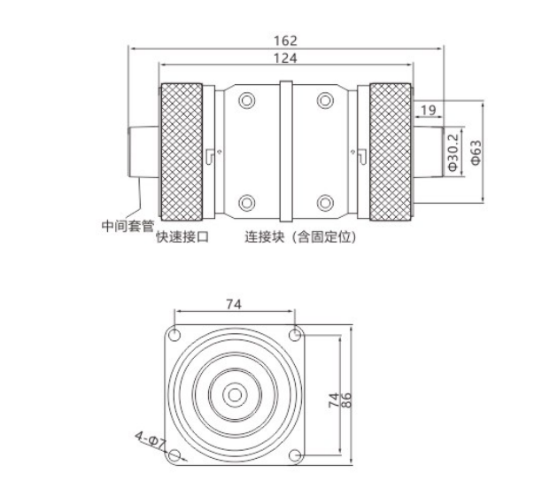
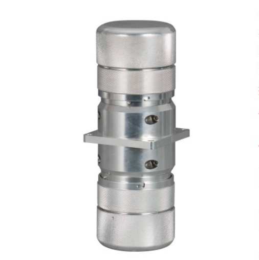
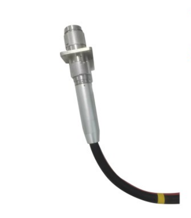
The 15kV Quick Release Intermediate Connector (with Flange, 15kV Quick release intermediate connector with flange) is a dedicated rapid-connection device designed specifically for live-line bypass operations in 10kV/15kV medium-voltage power distribution systems. Both ends employ standardized quick-connect/disconnect interfaces, and a fixed mounting flange is integrated at the center. This design enables rapid mating of two bypass cable segments with secure fixed installation, establishing a temporary bypass power supply circuit. The connector combines both connection and mounting functions, and is compatible with bracket-mounted installation scenarios. It serves as a core component in medium-voltage distribution live-line bypass operations.
Product Features
Electrical and Conductive Performance
The connector employs a high-purity copper conductive core, providing excellent conductivity with extremely low contact resistance. It supports a rated current of 200A/630A for sustained operation without thermal rise or oxidation, meeting the demands of high-current bypass power supply applications.
The conductive core utilizes an elastic contact structure with a large contact area and uniform contact pressure, capable of withstanding frequent mating/demating cycles. Contact performance remains stable with no risk of loosening or poor contact.
A built-in electric field optimization structure uniformly distributes the electric field at the interface, effectively suppressing partial discharge. Long-term operation presents no risk of electrical erosion or dielectric breakdown, ensuring stable and reliable electrical performance.
Structural and Safety Features
Both ends adopt standardized quick-connect/disconnect interface designs that strictly comply with industry standards. They are fully interchangeable with mainstream 15kV bypass cables and quick-connect equipment, offering strong compatibility and adaptability for constructing bypass circuits of various configurations.
The center-integrated fixed flange structure allows direct bolt-mounting to brackets or equipment enclosures, ensuring stable installation of the connector and preventing interface loosening caused by vibration or cable tension during operation.
The integrated modular design features a quick-lock connection mechanism that requires no additional tools, enabling rapid mating and demating of two bypass cable segments and significantly reducing bypass operation construction time.
The built-in self-locking anti-withdrawal structure automatically locks upon full interface insertion, preventing loosening or disengagement during operation and improving the reliability of circuit connections. The fully insulated protective design provides high outer insulation integrity, allowing safe contact with the housing during live operation with no risk of electric shock.
Environmental and Weather Resistance
The connector exhibits excellent weather resistance, suitable for a wide operating temperature range of -40°C to +90°C. Both the conductive core and the insulation layer maintain full performance at extreme temperatures with no risk of cracking or embrittlement, making it suitable for both outdoor and indoor operating environments.
Rated IP67 for moisture, water, dust, contamination, and salt-fog protection, the connector is capable of long-term stable operation in harsh environments including humid, dusty, and salt-fog conditions, with immunity to rainwater and condensation ingress.
The connector is resistant to aging and corrosion. The conductive core surface is tin-plated or silver-plated to prevent oxidative corrosion. Service life exceeds 10 years with maintenance-free operation, reducing long-term operational and maintenance costs.
Mechanical and Compatibility Features
The connector provides high mechanical strength with impact and vibration resistance, capable of withstanding mechanical stresses encountered during transportation, installation, and operation without risk of deformation or damage. The flange structure ensures secure mounting capable of withstanding defined tensile and torsional loads, suitable for bracket-fixed installation scenarios.
Compatible with 10kV/15kV bypass cables, bypass switches, transfer cables, and various other bypass operation equipment, providing strong versatility and flexible configuration for bypass circuits of varying lengths.
The modular design supports repeated mating/demating, facilitates convenient maintenance, and reduces equipment investment costs for bypass operations.
Technical Parameters
| Parameter Category | Item | Technical Specification |
| Rated Electrical Parameters | System Operating Voltage (Un) | 10kV/15kV |
| | Rated Voltage (Ue) | 15kV | |
| | Maximum Operating Voltage (Um) | 17.5kV | |
| | Rated Frequency (fn) | 50Hz/60Hz | |
| | Power Frequency Withstand Voltage | 42kV/5min (dry test), no breakdown, no flashover | |
| | Lightning Impulse Withstand Voltage | 95kV (peak), no breakdown, no flashover | |
| | Partial Discharge Level | ≤10pC (at 1.5U₀) | |
| | Rated Current | 200A/630A (selectable) | |
| | Rated Short-Circuit Withstand Current | 20kA/2s, 25kA/2s (selectable) | |
| | Contact Resistance | ≤20μΩ | |
| Structural and Material Parameters | Primary Material | Tin-plated/silver-plated copper (conductive core), high-strength insulating material (housing), stainless steel (locking mechanism/flange) |
| | Ingress Protection Rating | IP67 | |
| | Interface Standard | 15kV quick-connect/disconnect interfaces at both ends, center-mounted fixed flange, compliant with bypass operation equipment industry standards | |
| | Compatible Equipment | 10kV/15kV bypass cables, bypass switches, transfer cables, and other quick-connect bypass operation equipment | |
| | Flange Specification | Standard mounting flange (compatible with universal bracket/equipment mounting hole patterns; customization available) | |
| Environmental Parameters | Applicable Altitude | ≤2000m (high-altitude customization available) |
| | Ambient Temperature | -40°C to +90°C (operating), -40°C to +70°C (storage) | |
| | Relative Humidity | ≤100% (non-condensing) | |
| | Seismic Rating | Grade 8 | |
| Applicable Standards | GB/T 12706, DL/T 1476 Preventive Test Regulations for Electric Power Safety Tools and Equipment, DL/T 814 Distribution Automation Terminal |
Application Scope
Applicable Voltage Level: 10kV/15kV AC medium-voltage power distribution systems; suitable for bypass operation scenarios with a maximum operating voltage of 17.5kV.
Applicable Operating Scenarios:
Rapid mating of two bypass cable segments during live-line maintenance and modification operations on 10kV/15kV distribution lines and equipment, for extending bypass circuit length;
Bypass circuit scenarios requiring bracket-fixed installation (e.g., permanently mounted bypass interfaces in cable tunnels and distribution rooms), enabling stable connector installation;
Live-line bypass operations for urban distribution network cable circuits, industrial and mining enterprise power distribution systems, and renewable energy (photovoltaic/wind power) step-up substation distribution equipment.
Functional Purpose: To provide insulated isolation and conductive interconnection between two quick-connect bypass cable segments, while simultaneously enabling fixed installation of the connector via the flange structure, offering a flexible and stable circuit-building solution for live-line bypass operations in medium-voltage power distribution systems.
Operating Conditions
Standard Operating Conditions
Altitude: ≤2000m;
Ambient Temperature: -40°C to +90°C; equipment operating temperature complies with applicable standards;
Relative Humidity: ≤100% (non-condensing);
Environmental Conditions: Free of corrosive gases, flammable/explosive media, and severe vibration or shock;
Installation Method: Mounted via center flange bolts to a bracket or equipment enclosure; both ends are directly mated with corresponding bypass cable interfaces via plug-in connection; horizontal or vertical installation is permissible; installation space must accommodate mating/demating operations and flange mounting requirements.
Special Operating Conditions (Customization Required)
Altitude exceeding 2000m;
Ambient temperature outside the -40°C to +90°C range;
Severely polluted, salt-fog, or chemically corrosive environments;
High vibration or high shock operating conditions;
Non-standard interface specifications or non-standard flange mounting hole patterns;
Special current ratings or current-carrying capacity requirements.
Installation and Maintenance
Installation Requirements
Before installation, inspect the product for cracks, damage, and voids; verify the insulating housing is intact. Check that the conductive core, locking mechanism, and flange are free from rust, deformation, and that the locking mechanism operates smoothly and reliably.
Clean both connector interfaces and the corresponding bypass cable interface surfaces, removing grease, dust, and foreign matter to ensure interfaces are dry and clean. Clean the bracket/equipment enclosure mounting surface to ensure it is flat and clean.
Apply a uniform coat of dedicated silicone grease lubricant to the outer surface of both interfaces to prevent insulation layer damage during installation.
Mount the product to the bracket/equipment enclosure via the flange and tighten bolts to the specified torque. Securely connect both ends of the product to the corresponding bypass cable interfaces, ensuring full engagement. Engage the self-locking anti-withdrawal mechanism. Upon completion, verify no looseness or misalignment.
After installation, perform insulation resistance testing and power frequency withstand voltage testing. The product may be commissioned only upon passing these tests.
Maintenance Requirements
Periodically inspect the product for cracks, damage, discharge marks, and contamination buildup; verify secure connection at bypass cable interfaces with no loosening; check that flange mounting bolts show no loosening or corrosion.
Periodically test insulation resistance and contact resistance to confirm performance meets requirements and to detect potential faults in a timely manner.
Clean the product surface and interfaces, removing accumulated dust and contamination; maintain dry and clean insulating surfaces; avoid exposure to grease or chemical substances that may cause corrosion.
If the product exhibits abnormalities including cracks, damage, discharge, overheating, or contact resistance exceeding specified limits, immediately take it out of service and replace it. Operation of a defective unit is strictly prohibited.
Mating and demating of interfaces must be performed using dedicated insulating operating tools. Direct manual operation of energized interfaces is strictly prohibited. All operations must strictly comply with power distribution safety regulations.
Precautions
The product must be installed, commissioned, and maintained by qualified electrical professionals holding certifications for medium-voltage live-line bypass operations. Operation by unqualified personnel is strictly prohibited.
The product must be used with bypass operation equipment and mounting brackets of the corresponding specification. Mismatching equipment of different voltage ratings or current ratings is strictly prohibited, as this will result in insulation failure and safety hazards.
Unauthorized disassembly or modification of the product is prohibited and will void the warranty and safety guarantees. The use of non-dedicated tools to forcibly install or remove interfaces or flanges is strictly prohibited.
During installation, damage to the insulating surface must be strictly avoided. Silicone grease lubricant must be applied uniformly to avoid compromising insulation performance and sealing effectiveness. Flange mounting bolts must be tightened to the specified torque to prevent loosening that may cause connector vibration or interface disengagement.
During storage, the product must be kept in a dry, well-ventilated, and cool environment, away from direct sunlight, high temperatures, humidity, and compressive loads. Contact with sharp objects that may damage the insulating layer is strictly prohibited.
When mating or demating energized interfaces, all power distribution safety regulations must be strictly observed, adequate safety protective measures must be in place, and non-compliant operations are strictly prohibited.
Model Designation
| Model Identifier | Description |
|---|---|
| 15kV | Applicable system voltage level; rated voltage 15kV; maximum operating voltage 17.5kV |
| Quick release intermediate connector with flange | Flanged quick-connect intermediate connector for rapid mating and fixed installation of two bypass cable segments |
Applicable Standards and Certifications
International Standard: IEC 60840 Test methods and requirements for power cables with extruded insulation and their accessories for rated voltages above 30kV (Um=36kV) up to 150kV (Um=170kV);
National Standards: GB/T 12706 Power cables with extruded insulation and their accessories for rated voltages from 1kV (Um=1.2kV) up to 35kV (Um=40.5kV); DL/T 1476 Preventive Test Regulations for Electric Power Safety Tools and Equipment; DL/T 814 Distribution Automation Terminal;
The product has passed type testing by the National Electric Power Safety Tools and Equipment Quality Supervision and Inspection Center and complies with national electric power industry standards.
Section X. After-Sales Service
Product Warranty Period: 18 months from the date of manufacture, or 12 months from the date of commissioning, whichever comes first;
During the warranty period, product defects attributable to quality issues are repaired or replaced free of charge;
Technical support, installation guidance, and customization services are available (for special specifications and special operating condition adaptations).
Document Notes
The technical parameters in this manual are based on standard operating conditions. Special operating conditions require customization based on actual requirements. The product technical agreement and type test report shall prevail as the final authority.
Appendix: Product Outline Drawing