
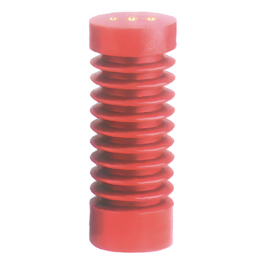
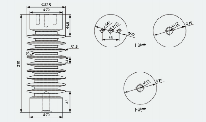
ZJ3-24Q/70*210 Post Insulator
Product Overview
The ZJ3-24Q/70*210 post insulator is an indoor insulation component designed for 24kV voltage systems. Manufactured using an epoxy resin casting process, it serves the dual functions of mechanical support and electrical insulation, effectively isolating live parts from grounded components and preventing current leakage. Widely used in high-voltage power distribution equipment, it offers key advantages such as resistance to pollution and moisture, as well as requiring no special maintenance, making it a critical component for electrical equipment such as high-voltage switchgear and metal-clad switchgear.
Product Features
(I) Electrical Performance
Material stability and strong aging resistance ensure a long service life, reducing long-term equipment maintenance costs.
Rated voltage of 24kV; power-frequency wet withstand voltage (1 min) ≥36kV; lightning impulse withstand voltage (peak) ≥75kV; meets insulation requirements for high-voltage equipment operation.
Excellent insulation performance with an insulation resistance ≥500MΩ (tested via 2500V megohmmeter); effectively resists flashover and breakdown, ensuring operational safety.
Epoxy resin material offers superior dielectric properties, resisting insulation aging and performance degradation during long-term operation.
(II) Mechanical Performance
Compact structure with high overall strength; capable of withstanding rated mechanical breaking loads; suitable for mounting and supporting indoor high-voltage equipment.
Equipped with dedicated threaded mounting holes at both ends for convenient, secure installation; compatible with various electrical equipment assembly configurations.
(III) Environmental and Weathering Performance
High pollution resistance; the surface resists dirt accumulation, maintaining excellent insulation performance even during long-term operation.
Resistant to moisture and temperature extremes; suitable for complex indoor environments with stable operation across a temperature range of -40°C to +40°C.
Core Technical Parameters
Applications
Applicable Scenarios: Three-phase AC indoor distribution systems with rated voltage of 10kV and below, at 50Hz, including:
Draw-out switchgear, ring main units, KYN28 and other high-voltage complete switchgear assemblies
Substation and distribution room switchgear
Insulation isolation and connection of live conductors passing through partitions, walls, and grounded structures
Compatible Busbars: Copper or aluminum busbars; maximum compatible busbar size 102×12mm. Busbars pass through the inner bore of the bushing to achieve electrical continuity.
Applicable Industries: Power utilities, industrial and mining enterprises, rail transit, new energy, and other distribution systems.
Operating Conditions
Normal Operating Conditions
Ambient Temperature: -25°C to +40°C, with daily average temperature not exceeding +35°C
Altitude: Not exceeding 1,000m (altitude correction per applicable standards required above 1,000m)
Relative Humidity: Not exceeding 85% at +20°C, non-condensing
Environmental Requirements: Free from gases, vapors, dust, explosive or corrosive media that would significantly impair insulation; free from severe vibration and shock
Installation Method: Indoor vertical or horizontal mounting, with flange bolted to switchgear partition
Special Operating Conditions (Custom Order Required)
High altitude, high humidity and heat, or heavily polluted environments
Extreme high or low temperature environments
Applications with special anti-corrosion or explosion-proof requirements
Installation and Maintenance
Installation Requirements
Pre-Installation Inspection: Verify that the bushing exterior shows no cracks, damage, or voids, that the flange face is flat, and that dimensions conform to installation requirements.
Aperture Fitting: The switchgear partition cutout must match the 125×125mm flange, with bolt hole positions pre-drilled.
Mounting and Fastening: Insert the bushing through the partition and secure the flange with bolts, ensuring a tight, gap-free fit with no looseness.
Busbar Installation: Pass the busbar through the inner bore of the bushing, maintaining uniform clearance between the busbar and the inner bore wall to avoid localized stress concentration.
Clearance Requirements: After installation, verify that the safety clearances between energized parts at both ends of the bushing and grounded components meet 10kV system requirements.
Maintenance Requirements
Routine Inspection: Periodically check the bushing surface for contamination buildup, discharge marks, and cracks, and check the flange for looseness.
Cleaning and Maintenance: Clean surface contamination with a dry soft cloth. Use of corrosive cleaning agents is strictly prohibited to avoid damage to the insulation body.
Periodic Testing: Conduct insulation resistance and power-frequency withstand voltage tests at intervals specified by preventive testing standards for electrical equipment to ensure continued compliance.
Replacement Criteria: Immediate replacement is required upon occurrence of insulation breakdown, severe surface discharge, or mechanical cracking.
Precautions
Operation above rated voltage or outside specified environmental conditions is strictly prohibited to prevent insulation failure.
All installation and maintenance work must strictly comply with high-voltage electrical safety procedures and must be performed with the equipment de-energized.
During transportation and storage, protect against impact and compression to prevent damage to the insulation body; store in a dry, well-ventilated environment.
This product is intended for indoor use only; direct use in outdoor exposed environments is prohibited (outdoor-rated versions require custom order).
Striking or force-fitting the bushing during installation is strictly prohibited to avoid internal micro-cracking.
Quality Assurance
This product conforms to relevant national standards and undergoes 100% factory inspection, with quality inspection reports provided. Under normal operating conditions, the warranty period is as stipulated in the contract. Quality issues arising from causes other than misuse or operation outside specified conditions are covered under after-sales warranty service.
Product Image
| Parameter | Specification / Value | Notes |
|---|---|---|
| Model | TG1-10Q/210(125×125) | Industry-standard model designation |
| Rated Voltage | 10kV (maximum operating voltage 12kV) | Applicable to 10kV three-phase AC systems |
| Rated Frequency | 50Hz (compatible with 15–60Hz) | Compatible with power-frequency distribution systems |
| Flange Dimensions | 125×125mm | Flange side length; matches standard switchgear cutout |
| Overall Height | 210mm | Total axial length of product |
| Compatible Busbar | Copper busbar 102×12mm and below | Inner bore dimensions matched to corresponding busbar sizes |
| Insulation Material | Epoxy resin (APG process molded) | Red insulation body |
| Power-Frequency Withstand Voltage | 42kV / 1 min | One-minute power-frequency withstand voltage |
| Lightning Impulse Withstand Voltage | 75kV (peak) | Standard lightning impulse withstand voltage |
| Creepage Distance | ≥210mm | Meets 10kV system insulation requirements |
| Thermal Class | Class F (continuous maximum 155°C; short-term withstand 300°C) | Compatible with switchgear operating temperature rise |
| Applicable Standards | GB/T 12944.1, GB/T 12944.2 | National standards for high-voltage through-wall bushings |
Product Information
Application
This insulation or sensing component is intended for switchgear, busbar, contact-box, bushing, sensor, or cabinet-support applications according to the matched model.
Product Images
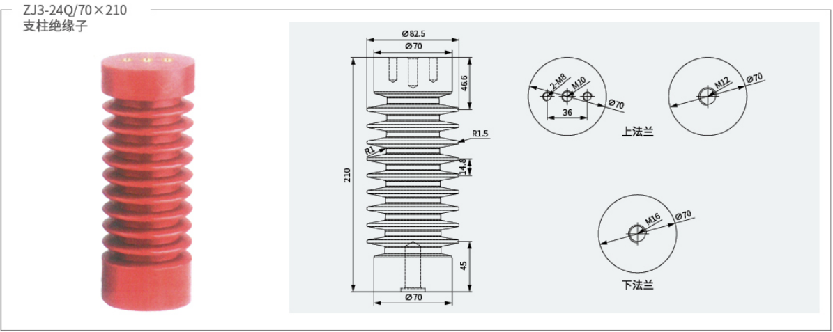
Technical Parameters
| Parameter Category | Source specification | Remark |
|---|---|---|
| Product Model | ZJ3-24Q/70×210 | – |
| Rated Voltage | 24kV | Source specification |
| Height | 210mm | Height |
| Source specification | 70mm | Insulation Diameter |
| Material | Epoxy Resin | Source specification |
| Mounting Method | Securing | Installation |
| ApplicableAmbientTemperature | -40°C~+40°C | – |
| Altitude | ≤1000m | StandardAmbientApplicable |
| WithstandVoltage | ≥36kV(1min) | RMS |
| Lightning Impulse Withstand Voltage | ≥75kV(Peak) | – |
| Insulation Resistance | ≥500MΩ | 2500V |
Order information
Before ordering, confirm model, rated voltage, rated current, installation dimensions, interface type, accessory requirements, and the required quantity according to the project drawings and source specification.