نظرة عامة على المنتج
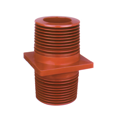
جلبة الحائط TG3-35Q/260×260×450 هو مكون عازل من راتنج الإيبوكسي مصمم لأنظمة الطاقة ذات الجهد العالي 35 كيلو فولت.
It allows live conductors, such as busbars and copper bars, to pass safely through walls, partitions, switchgear panels, and other grounded structures. The bushing provides electrical insulation, mechanical support, and a stable passage for conductor connections, helping ensure the safe and reliable operation of high-voltage power systems.
مناسب للاستخدام في محطات الطاقة، والمحطات الفرعية، والجهد العالي switchgear، وغرف التوزيع، وغيرها من التركيبات الكهربائية ذات الجهد المتوسط.
المواصفات الفنية
| معامل | مواصفات |
|---|---|
| موديل المنتج | TG3-35Q/260×260×450 |
| الجهد المقنن | 40.5 kV, suitable for 35 kV systems |
| التردد المقنن | 15–60 Hz |
| التيار المقنن | 630–3150 A, customizable upon request |
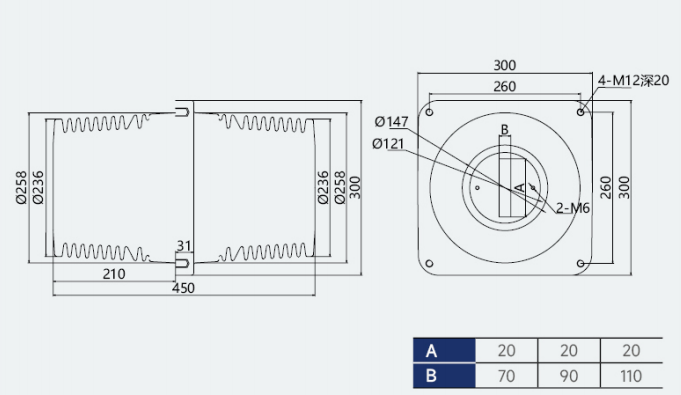
| الأبعاد الكلية | 260 × 260 × 450 mm |
| Mounting Flange Size | 260 × 260 mm |
| مادة | Epoxy resin manufactured by APG process |
| Colour | Red |
| جهد تحمل التردد الكهربائي | 95 kV for 1 minute under dry conditions |
| جهد تحمل النبضات البرقية | 185 kV peak |
| التفريغ الجزئي | ≤5 pC at 1.1 Um |
| مسافة الزحف | Complies with the applicable requirements of GB/T 311 and related standards |
| Optional Configuration | Integrated internal shielding layer |
ميزات المنتج
Excellent Electrical Insulation
The wall bushing is manufactured through an integrated epoxy resin Automatic Pressure Gelation process. The dense moulded structure helps minimize internal bubbles, voids, and other insulation defects.
Its high dielectric strength provides reliable resistance to electrical breakdown in 35 kV power systems.
The external shed structure increases the creepage distance and improves resistance to surface tracking, moisture, contamination, and flashover.
قوة ميكانيكية موثوقة
The epoxy resin body provides good resistance to impact, bending, cracking, and mechanical deformation.
It can withstand the electrodynamic forces generated by busbars during short-circuit conditions, helping maintain conductor alignment and structural stability during long-term operation.
The square mounting flange distributes mechanical loads evenly and provides a firm connection to switchgear panels, walls, or equipment partitions.
Optimized Electric Field Distribution
An internal shielding layer can be integrated according to application requirements. The shielding structure helps distribute the electric field more evenly, reduce local electric field concentration, and suppress partial discharge.
The smooth internal and external surfaces contain no sharp edges, helping reduce corona discharge and improve long-term insulation reliability.
قدرة عالية على التكيف البيئي
The epoxy resin material provides resistance to:
- High and low temperatures
- Electrical ageing
- Moisture
- Chemical corrosion
- Mould and fungal growth
- Insects and other biological influences
- Common industrial contaminants
The product can be used in indoor, outdoor, high-altitude, and industrial power distribution environments, subject to the selected creepage distance and installation configuration.
تركيب وصيانة مريحة
The standardized flange dimensions and mounting-hole arrangement allow the bushing to be installed in compatible 35 kV switchgear, including KYN61-40.5 and similar cabinet structures.
Its compact and lightweight design simplifies installation. Under normal operating conditions, routine maintenance is limited mainly to surface cleaning and connection inspection.
تطبيقات
The TG3-35Q/260×260×450 Wall Bushing is suitable for three-phase AC power systems with rated voltages from 10 to 35 kV and frequencies from 15 to 60 Hz.
تشمل التطبيقات النموذجية:
- Busbar passage connections inside high-voltage switchgear
- KYN61-40.5 and similar 35 kV switchgear
- Busbar connections through substation walls and partitions
- Power distribution room wall penetrations
- Box-type substations
- وحدات الحلقة الرئيسية
- Busbar and conductor insulation support
- Industrial high-voltage distribution systems
- Mining power distribution systems
- Petrochemical electrical installations
- Power stations and substations
The bushing can be used wherever a live conductor must pass through a grounded wall, metal panel, equipment partition, or insulating barrier.
ظروف التشغيل
Normal Environmental Conditions
| Condition | Requirement |
|---|---|
| درجة الحرارة المحيطة | -40°C to +120°C |
| Short-Term Temperature Resistance | Up to +155°C |
| Installation Altitude | ≤3,000 m |
| Daily Average Relative Humidity | ≤95% |
| Monthly Average Relative Humidity | ≤90% |
| Pollution Level | Up to Level IV |
| بيئة التثبيت | Free from severe vibration, impact, explosive substances, and strongly corrosive gases |
For installations above 3,000 metres, equipment derating, insulation coordination adjustment, or a customized bushing may be required.
For heavily polluted environments, a model with an increased creepage distance should be selected.
متطلبات التثبيت
Installation Direction
The wall bushing can be installed vertically or horizontally.
The flange surface must fit closely against the switchgear panel, wall, or mounting partition. All fastening points should be tightened evenly to avoid mechanical stress and deformation.
Conductor Installation
When inserting a copper bar or busbar through the bushing, maintain an even clearance between the conductor and the inner surface.
The conductor must be correctly centred to prevent localized mechanical stress and uneven electric field distribution.
Do not force an oversized or misaligned conductor through the bushing.
Sealing and Protection
Install a suitable sealing gasket between the flange and the mounting surface.
The seal helps prevent dust, moisture, and contaminants from entering the equipment compartment and improves long-term insulation reliability.
الخلوص الكهربائي
After installation, verify the clearance between live conductors and grounded structures.
The completed assembly must meet the minimum electrical clearance and insulation coordination requirements specified in GB/T 311 and other applicable standards.
Fastening Requirements
Use suitable mounting bolts and tighten them according to the equipment assembly specifications.
Excessive tightening may damage the epoxy resin flange, while insufficient tightening may result in vibration, loosening, or uneven mechanical loading.
Inspection and Maintenance
فحص ما قبل التركيب
Before installation, confirm that:
- The model and dimensions match the equipment design
- The flange dimensions and mounting holes are compatible
- The surface is clean and dry
- No cracks, chips, deformation, or impact damage are present
- The internal passage is free from foreign objects
- Required electrical inspection results are acceptable
- The conductor size matches the internal opening
Do not install a bushing with visible damage or suspected insulation defects.
Routine Inspection
During scheduled equipment maintenance:
- Clean contamination from the insulating surface
- Check the flange mounting bolts for looseness
- Inspect the surface for cracks or deformation
- Check for electrical tracking marks
- Check for carbonization or arc damage
- Inspect for abnormal partial discharge
- Confirm that the conductor remains correctly positioned
- Check the condition of the flange sealing gasket
Use a clean, dry, soft cloth for routine cleaning. Do not use corrosive solvents, metal tools, or abrasive cleaning materials.
Replacement Conditions
Stop operation and inspect or replace the wall bushing immediately if any of the following conditions are found:
- Visible cracks
- Severe surface damage
- Carbonization
- Electrical tracking
- Arc erosion
- Abnormal partial discharge
- Mechanical deformation
- Loose or damaged conductor connections
- Significant deterioration of insulation performance
احتياطات السلامة
- Avoid impact, dropping, compression, and improper stacking during transportation.
- Store the product in a dry, ventilated environment free from corrosive gases.
- Protect the insulating surface from moisture, oil, dust, and mechanical damage.
- Do not drill, cut, grind, or otherwise modify the bushing without technical approval.
- Do not install or remove the product while the equipment is energized.
- Disconnect and isolate all power sources before installation or maintenance.
- Confirm that the circuit is de-energized and properly grounded before work begins.
- Installation and maintenance must be carried out by qualified electrical personnel.
- Stop operation immediately if partial discharge, tracking marks, cracks, or other insulation abnormalities are detected.
Selection and Ordering Information
When selecting the TG3-35Q/260×260×450 Wall Bushing, confirm the following information:
- System rated voltage
- التيار المقنن
- Conductor or busbar dimensions
- Installation direction
- Mounting flange dimensions
- Available installation space
- Required creepage distance
- Environmental pollution level
- Installation altitude
- Need for an internal shielding layer
- Indoor or outdoor operating conditions
Customized rated current, conductor openings, creepage distances, shielding structures, and mounting dimensions are available according to project requirements.