
Medium voltage switchgear often uses separable cable connections to create a compact, screened, and serviceable interface between the incoming or outgoing cable and the equipment bushing. In higher-current circuits, a deadbreak connector is a common solution because it provides a secure cable-to-equipment connection without being intended for routine load switching.
Choosing the right deadbreak connector, however, involves more than matching a voltage class and current rating. The switchgear bushing interface, cable construction, conductor size, insulation diameter, connection layout, grounding arrangement, and operating procedure all affect whether the completed connection will perform as intended.
At YIEOU, we manufacture medium voltage cable accessories for both American-style and European-style connection systems. Our product range includes 15kV and 24kV 600A deadbreak connector components, together with related bushings, busbars, insulated caps, grounding accessories, and other components used in medium voltage cable connection systems.
Quick answer
For medium voltage switchgear, the correct deadbreak connector should be selected around the actual equipment interface first, followed by system voltage, continuous current, cable conductor and insulation dimensions, shielding and grounding requirements, and the physical cable compartment. A 600A connector and a 630A connector may serve similar high-current applications, but they should not be considered interchangeable unless the interface standard and equipment dimensions also match.
Why Are Deadbreak Connectors Used in Medium Voltage Switchgear?
A switchgear cable connection has to do several jobs at the same time. It carries the normal operating current, maintains the required insulation level, controls electrical stress around the cable termination, and provides a mechanically stable transition from the cable into the switchgear.
A deadbreak Separable Connector combines these functions in a removable connection system.
A practical connection for higher-current feeders
Deadbreak connectors are commonly associated with higher-current feeder and equipment connections. A 600A deadbreak system, for example, can be used where the switchgear circuit carries considerably more current than a typical 200A loadbreak lateral connection.
The connector is attached to a compatible equipment bushing or related interface, while the cable conductor is terminated through the connector contact system. Once properly assembled, the connection becomes part of the main electrical path rather than simply acting as an insulated cover around a cable end.
This makes deadbreak connectors suitable for applications such as:
- medium voltage switchgear incoming and outgoing feeders;
- ring main units and compact switchgear;
- transformer-to-switchgear cable connections;
- compact substations;
- cable distribution equipment; and
- underground medium voltage distribution systems.
Screened construction supports compact equipment
Space inside modern switchgear is often limited. Compared with an open-air termination, a screened Separable Connector can provide a more controlled connection arrangement around the equipment bushing.
The connector body normally incorporates insulation, stress-control features, and an outer conductive screen that is connected to earth as part of the completed installation. This helps control the electrical field around the connection and allows the cable interface to fit into compact switchgear compartments.
It does not remove the need for correct grounding, installation clearance, or cable preparation. The entire connection system still has to be installed according to its design and the switchgear manufacturer’s arrangement.
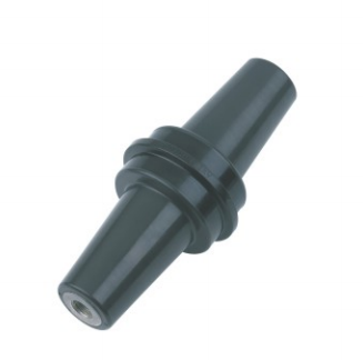
Deadbreak and Loadbreak Connectors Are Not the Same
One of the first decisions is whether the switchgear connection actually requires a deadbreak or loadbreak function.
Although both belong to the broader Separable Connector family, their operating functions are different.
Deadbreak means the connection is not intended to interrupt load current
A deadbreak connector must not be disconnected while carrying load current.
Before separation, the applicable system must be de-energized and isolated, absence of voltage must be verified, and grounding or other safety measures must be applied according to the operating procedure for the installation.
The word *separable* therefore should not be interpreted as meaning the connector can simply be unplugged whenever required.
Its advantage is that the cable-to-equipment interface can be separated when the system has been placed in the correct safe condition. This can support equipment replacement, cable testing, system modification, and planned maintenance without turning the cable connection into a permanent joint.
Loadbreak connectors have a different operating purpose
A loadbreak connector is designed as part of a system capable of specified load-make or load-break operations under defined ratings and procedures.
This type of function is more commonly associated with certain lower-current distribution interfaces, such as 200A-class elbow connector systems.
Where the switchgear circuit is designed around a high-current main feeder and load switching is already performed by the switch or circuit breaker inside the switchgear, a deadbreak connection is often the more appropriate cable interface.
The switching device and the cable connector therefore perform different roles. The breaker or switch controls the circuit; the deadbreak connector provides the insulated and screened cable connection.
Start with the Switchgear Bushing Interface
For a deadbreak connector, the equipment interface is one of the most important selection points.
Two connectors can have similar voltage and current ratings while using completely different interface dimensions. Forcing a connector onto the wrong bushing is not an acceptable way to solve an interface mismatch.
Identify the interface from the equipment specification
Switchgear drawings normally provide information about the cable bushing, interface standard, current rating, and sometimes the intended connector family.
That information is more reliable than identifying the interface from appearance alone.
The bushing determines how the connector mechanically fits the switchgear, where the electrical contact is made, and how the insulation interface is formed. The connector, bushing, fastening components, and any coupling accessories must therefore belong to a compatible system.
American-style 600A deadbreak systems
American-style separable insulated connector systems are commonly associated with IEEE interface requirements.
The current IEEE 386-2025 standard covers shielded loadbreak and deadbreak separable insulated connector systems for distribution systems from 2.5kV through 35kV and up to 900A.
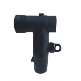
A 600A deadbreak arrangement may include a T-body connector together with a compatible bushing, connecting plug, junction, insulated protective cap, or other system accessories depending on the switchgear configuration.
When the equipment uses this type of interface, the complete connection should remain within the compatible interface family.
European-style 630A Interface C systems
European switchgear commonly uses standardized outer-cone separable interfaces. Interface C, as described within the EN 50180/EN 50181 connection system, is widely used for 630A-class separable T-connectors on transformers and medium voltage switchgear. Commercial Interface C systems are available for 630A service and may support higher ratings when matched with the corresponding bushing design.
A European-style 630A Interface C connector may perform a similar practical role to a 600A deadbreak connector, but the two belong to different interface systems.
When a switchgear drawing specifies a 600A IEEE-style deadbreak interface, a 630A Interface C connector should not be treated as a near-equivalent simply because the current values are close. The bushing geometry, contact arrangement, fastening method, dimensions, and applicable standards also have to match.
That distinction is particularly important when accessories are being selected for switchgear from different markets.
Match the Connector to the Cable as Well as the Switchgear
Once the equipment interface is confirmed, attention moves to the cable.
The same switchgear bushing may be connected to several cable sizes, but this does not mean that one connector kit automatically fits every cable.
Conductor size and conductor material
The conductor connection must suit the cable cross-section and conductor material.
Medium voltage cables may use copper or aluminium conductors, and the contact or conductor connector used inside the deadbreak system has to be suitable for the intended combination.
Depending on the connector design, this may involve a compression connector, mechanical connector, shear-bolt arrangement, or another specified contact system.
The selected component should provide the required electrical contact without damaging the conductor or creating an unstable contact resistance.
Cable insulation diameter is especially important
Conductor cross-section alone is not enough to identify a suitable Separable Connector.
Two cables with the same conductor area can have different insulation diameters because of differences in voltage class, insulation design, manufacturer, or cable construction.
The connector’s cable adapter, reducer, stress-control section, or sealing region has to fit the actual insulation diameter.
If this part of the connector is too large or too small for the prepared cable, the intended interface pressure and electric-field control can be affected.
For this reason, cable insulation diameter is one of the dimensions we pay close attention to when matching medium voltage separable cable accessories.
Screen construction also affects the installation
The cable may use copper wire screen, copper tape screen, or another metallic screen arrangement. Its semiconductive insulation screen and outer sheath construction also influence how the cable is prepared.
The connector’s earthing lead and conductive screen need to work with the cable’s grounding arrangement so that the completed connection maintains the intended screened structure.
Correct cable preparation is therefore just as important as choosing the right connector model.
Voltage and Current Ratings Need to Be Read in Context
Voltage and current labels are essential, but they should not be used independently of the rest of the system.
Match the complete insulation level
A connector selected for medium voltage switchgear should correspond to the system’s rated voltage and maximum system voltage, together with the insulation requirements specified for the equipment.
A connector marked for a higher nominal voltage is not automatically compatible with a lower-voltage switchgear interface. The physical bushing family and connector design still have to match.
For IEC-type cable systems, accessory testing for extruded-insulation power cables up to Um=36kV is covered by IEC 60502-4:2023. The standard addresses type-test requirements for cable accessories rather than defining compatibility merely through a nominal voltage label.
Continuous current is only part of the current requirement
A 600A or 630A rating describes the connector system’s continuous-current capability under its specified conditions.
Actual performance also depends on the contact connection, cable conductor, installation temperature, switchgear compartment temperature, connection resistance, and surrounding components.
Short-circuit requirements should be checked separately rather than inferred from the continuous-current number.
A connector carrying 600A continuously does not mean that every component associated with it automatically has the same short-circuit withstand characteristics as the switchgear or cable.
The complete connection needs to satisfy the project fault-current requirements.
Avoid unnecessary oversizing
Selecting a higher current rating than the circuit requires does not solve an interface problem.
If the switchgear is designed for a particular deadbreak interface, moving to another interface family simply because its current number is higher can create more problems than it solves.
Interface compatibility, insulation level, cable fit, and system design should remain the basis of the selection.
Screening, Grounding, and Installation Conditions Matter
A deadbreak connector operates as an integrated insulation system. Its reliability depends heavily on installation quality.
The conductive screen must be correctly grounded
A screened connector usually has an external conductive layer designed to be connected to earth.
This screen helps establish a controlled electrical environment around the connector body. The grounding lead, cable metallic screen, and switchgear earthing arrangement therefore need to be coordinated.
An unconnected or incorrectly connected screen changes the intended behaviour of the connector system.
Clean interfaces are critical
The mating surfaces between the connector and bushing must remain clean and free from damage.
Dust, metal particles, moisture, damaged insulation surfaces, or incorrect installation materials can reduce dielectric performance.
Where an installation instruction specifies a particular cleaning method or lubricant, that instruction should be followed rather than substituting an arbitrary grease or installation compound.
Cable bending should not load the connector
Switchgear cable compartments can be narrow, especially when large cross-section medium voltage cables enter from below.
The cable bending radius and routing should be planned so that the cable does not continuously pull the deadbreak connector sideways or place unnecessary mechanical stress on the equipment bushing.
The connection may fit electrically while still being unsuitable mechanically if the cable has to be forced into position.
Enough room should also remain for installation tools, connector assembly, grounding, inspection, and later removal.
Consider the Complete Switchgear Connection Layout
The connector body is only one component of the cable connection.
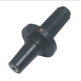
The final arrangement may also require bushings, coupling connectors, busbars, protective caps, grounding accessories, surge protection components, or provisions for an additional cable.
Single-cable feeder connections
For a straightforward incoming or outgoing feeder, one deadbreak connector per phase may connect directly to the corresponding switchgear bushing.
A T-shaped Separable Connector is commonly used because the cable can enter from below while the connection is secured to the equipment interface.
The exact orientation still depends on the switchgear compartment and connector system.
Dual-cable arrangements
Some switchgear circuits require two cables per phase.
In this case, the solution should use a connector system specifically designed for an additional connection, such as compatible coupling components, rear connectors, connecting plugs, or an approved bus/junction arrangement.
Simply adding another connector to an interface that was not designed for it can affect mechanical support and electrical performance.
European Interface C systems, for example, can use compatible front and rear or coupling connector arrangements for dual-cable applications. American-style deadbreak systems use their own corresponding accessories.
The two methods should not be mixed simply because both may appear T-shaped.
Spare and unused interfaces
A spare switchgear interface should not be left exposed.
Where the system includes an unused bushing or reserved connection point, an insulated protective cap or dead-end component matched to that interface should be installed.
This preserves the intended insulation arrangement while keeping the connection point protected from contamination.
Mixed 200A and 600A connections
Some distribution layouts use both 200A and higher-current interfaces.
These should be connected through purpose-designed bushings, junctions, busbars, or transition components rather than by assuming that one Separable Connector can directly mate with another current class.
This becomes particularly important in compact substations and cable branch systems where several connection functions are grouped into a small area.
YIEOU Deadbreak Connector Manufacturing for Medium Voltage Switchgear
For us, a deadbreak connector is not an isolated rubber component. It is part of the complete connection between the medium voltage cable and the switchgear.
That is why our matching process considers the connector together with the equipment interface, cable dimensions, contact components, grounding structure, busbar or bushing arrangement, and any additional accessories required by the installation.
Our current medium and high voltage cable accessory range includes American-style and European-style products, together with cold-shrink accessories, cable branch products, bushings, connectors, arresters, and supporting connection components. Our production and quality-control facilities include dedicated partial-discharge testing facilities, withstand-voltage testing equipment, and equipment for material and electrical-performance inspection.
For medium voltage switchgear projects, this system-based approach is particularly useful because the same general term — deadbreak connector or Separable Connector — can refer to very different actual interfaces.
A reliable selection therefore starts with the equipment drawing and cable data, then works outward to the complete accessory arrangement.
When the interface, cable, connector, grounding system, and switchgear layout are coordinated from the beginning, installation becomes more predictable and the completed connection is better suited to long-term service.
FAQ
Is a deadbreak connector a Separable Connector?
Yes. A deadbreak connector is a type of Separable Connector used to create a removable insulated connection between a medium voltage cable and compatible equipment such as switchgear, transformers, ring main units, or cable distribution equipment.
The term *deadbreak* describes its operating characteristic: the connection is not designed to be separated while carrying load current.
Can a 600A deadbreak connector be disconnected under load?
No. A 600A deadbreak connector should not be disconnected while energized and carrying load current.
The circuit must first be placed into the required safe condition according to the applicable operating procedure, including isolation, voltage verification, and grounding where required.
Load switching should be performed by equipment designed for that function.
Is a 630A Interface C connector interchangeable with a 600A deadbreak connector?
Not simply because their current ratings are similar.
A 600A IEEE-style deadbreak connection and a 630A EN 50180/EN 50181 Interface C connection belong to different interface families. The switchgear bushing, dimensions, contact arrangement, fastening method, and connector system must all be compatible.
The equipment interface should therefore be identified before selecting the connector.
What cable information affects deadbreak connector selection?
Important cable information includes conductor cross-section, copper or aluminium conductor material, cable voltage class, insulation diameter, metallic screen construction, and cable design.
The insulation diameter is particularly important because cables with the same conductor cross-section may still require different cable adapters or connector sizes.
Are T-body connectors suitable for medium voltage switchgear?
Yes, T-body separable connectors are commonly used for medium voltage switchgear connections, particularly in higher-current screened cable systems.
However, the T-body must match the switchgear bushing interface and cable specification. The fact that two connectors have a similar T-shaped appearance does not confirm compatibility.
What should be confirmed when selecting a YIEOU deadbreak connector for switchgear?
We normally match the connection around the switchgear interface, rated voltage, required current, cable conductor size and material, insulation diameter, screen construction, cable quantity per phase, and the available installation space.
From there, the deadbreak connector can be coordinated with the appropriate bushing, busbar, protective cap, grounding component, or other Medium Voltage Cable Accessories required by the final switchgear layout.