
A 35kV cable entry can be electrically rated for the project and still be impossible to assemble if the equipment socket, plug-in terminal, cable conductor contact, or working clearance belongs to a different system. We see this mismatch when a drawing identifies the voltage and feeder current but leaves the inner-cone interface size or cable dimensions unresolved. In our work with switchgear, ring main units, and prefabricated substations, we treat an Inner Cone Connector as part of one matched equipment-to-cable interface. The equipment socket establishes the geometry. The terminal then has to match the socket, the cable, the current path, and the available installation space.
Quick Answer
Select an Inner Cone Connector by confirming the equipment-side socket first. Start with the system voltage, maximum operating voltage, interface size, rated current, and the exact inner-cone socket fitted to the switchgear. Then match the cable conductor material and construction, conductor cross-section, diameter over insulation, screen design, and the space needed to insert and secure the terminal.
At YIEOU, our inner-cone range includes a 35kV plug-in terminal for 40.5kV-class equipment and matching inner-cone sockets in defined size series. We manufacture the terminal as one part of a complete connection that also uses the correct conductor contact, cable-side stress-control parts, sealing arrangement, grounding provisions, and protection for any unused socket. An Inner Cone Connector cannot be selected from a voltage label or cable cross-section alone.
Confirm the Equipment Socket Before Choosing the Terminal
The equipment drawing is the strongest starting point because the socket fixes the mating geometry. A specification that says only “35kV cable connector” does not identify the inner-cone size, contact arrangement, insertion depth, locking method, or mechanical envelope. Those details determine whether the terminal can seat correctly and whether the conductive and insulating interfaces reach their designed positions.
The socket series and its equipment drawing define the terminal geometry. In our JY NZ-35(40.5)-□ range, the terminal is designed for 35kV systems with a maximum operating voltage of 40.5kV and is available for matching #1, #2, or #3 inner-cone insulated sockets. The blank in the model identifies the required size series. This makes the size designation a functional part of the interface rather than a catalog suffix.
Our Inner Cone Connector configuration therefore follows the socket actually installed in the switchgear or other distribution equipment. The same nominal voltage does not make two socket sizes interchangeable. We keep the terminal, socket, and protective accessories within the same defined interface system so their mating surfaces and contact positions agree.
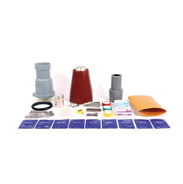
The socket assembly shown above illustrates how the equipment side fixes the connection geometry. The flange, epoxy body, conductive insert, seals, and mounting hardware form the connection base. A cable terminal that looks close to the opening can still have the wrong taper, insertion length, or contact position.
When we configure an Inner Cone Connector, we use the socket drawing to keep those hidden mating details connected to the correct terminal size.
Treat the Connection as One Matched Interface Chain
The Inner Cone Connector is only one part of the current path. On the equipment side, the socket has to be mounted and sealed correctly. Inside the terminal, the conductive contact has to fit the cable conductor and align with the equipment contact. On the cable side, the insulation interface and stress-control parts have to fit the prepared cable dimensions. The outer screening and grounding arrangement then complete the connection.
We treat the socket, terminal, conductor contact, adapter, stress-control parts, fastening pieces, and protective accessories as one interface system. Each part has a different function, but all of them depend on the same voltage class, socket series, cable construction, and installed orientation. Keeping that relationship clear in our product configuration prevents a correctly rated individual part from being combined with the wrong mating geometry.
Table 1. Components in a 35kV Inner Cone Connection
| Connection element | Main selection basis | What a mismatch can affect |
|---|---|---|
| Equipment socket | Voltage class, inner-cone size, contact position, flange and equipment drawing | Seating, insulation interface, conductive engagement, enclosure sealing |
| Plug-in terminal | Matching socket series, rated current, cable configuration, installation orientation | Complete insertion, locking, electrical stress control, mechanical fit |
| Conductor contact | Copper or aluminum conductor, cross-section, strand construction, connector design | Crimp or shear-bolt fit, contact pressure, current path, temperature rise |
| Cable-side adapter and stress control | Actual diameter over insulation, insulation material, screen construction | Interface pressure, sealing, stress distribution, surface condition |
| Grounding and screening parts | Product design, equipment grounding plan, cable screen arrangement | Screen continuity, touch potential control, maintenance identification |
| Protective plug for an unused socket | Exact socket series, voltage class, grounding arrangement | Insulation, sealing, contamination protection, clear spare-interface status |
The table shows the physical relationships within an Inner Cone Connector system. The final component set remains tied to the equipment drawing, cable datasheet, and the verified product configuration rather than to a generic list of 35kV accessories.
This is why our Inner Cone Connector range is organized around compatible interface families rather than voltage labels alone.
Match Voltage Current and Operating Duty Separately
Voltage class and rated current answer different questions. Our JY NZ product data identifies a 35kV system rating, a maximum operating voltage of 40.5kV, and available current classes of 630A or 1250A depending on the selected configuration. These values define the product family boundary, but they do not replace interface or cable matching.
The rated current follows the equipment circuit and complete current path. A 1250A switchgear bus does not prove that every cable feeder or Inner Cone Connector position uses a 1250A terminal. Conversely, fitting a higher-current terminal does not upgrade a 630A cable connection if the socket, contact system, cable, and equipment rating remain unchanged. We define the terminal configuration within the continuous and short-circuit duties of the complete connection.
Operating duty is another separate point. An Inner Cone Connector is a detachable cable interface, but detachable does not mean loadbreak. We do not present this inner-cone terminal as a device for switching load current. The switchgear or another approved switching device performs circuit interruption, and connector work follows the isolation, verification, grounding, and access procedure for the installation.
Terms such as plug-in, separable, and touchable describe structure or accessibility within a defined system. They do not authorize a field operating method. Our product definition remains separate from the switching function of the equipment, while the product instruction, equipment manual, and site safety procedure govern how the interface is installed, tested, isolated, or removed.
Cable Dimensions Decide the Final Connector Configuration
After the socket identifies the Inner Cone Connector family, the cable determines the parts on the cable side. Conductor cross-section is important, but it does not define the insulation diameter, screen structure, strand compaction, or conductor material. Two cables marked 240 mm² can require different contacts or adapters.
For the cable-side configuration, we use the voltage designation, conductor material, conductor construction, nominal cross-section, measured or manufacturer-stated diameter over conductor, diameter over insulation, insulation material, and screen design. The prepared dimensions follow the terminal instruction rather than a generic cable-stripping chart. A dimension taken at the wrong layer can lead to the wrong adapter even when the cross-section appears correct.
Copper and aluminum conductors also need the contact intended for their material and construction. In our Inner Cone Connector range, copper or aluminum conductive inserts are available configurations. We define the actual contact together with its conductor range and preparation method because a general “Cu/Al suitable” description does not establish how the cable and terminal will join.
Our Inner Cone Connector selection is complete only when the equipment size and cable-side configuration agree. The cable data describes what enters the compartment, while the switchgear socket drawing describes the fixed interface that our terminal must mate with. Both sides have to describe the same physical connection.
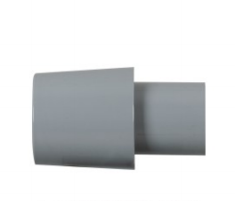
The terminal body is visually simple, but the hidden taper, internal contact position, and cable preparation dimensions control the fit. Visual similarity between two plug-in bodies is not a compatibility test.
For each Inner Cone Connector configuration, we keep the terminal geometry and cable-side parts tied to the same verified dimensional range.
Compartment Layout Must Allow Full Insertion and Cable Support
The Inner Cone Connector needs a straight and controlled installation path into the socket. The cable must approach the interface without forcing the terminal sideways, twisting the prepared cable, or placing continuous bending load on the socket. A correct electrical match can still fail the layout review if the cable entry plate, enclosure wall, neighboring phase, or gland position blocks the installation path.
In our application work, an Inner Cone Connector is evaluated in its installed orientation because the same terminal can face very different cable forces in a vertical or side-entry compartment.
The equipment drawing needs to allow for the installed Inner Cone Connector length, cable exit direction, minimum cable bending requirement, and the clearance needed for installation tools. Cable cleats or supports carry the cable weight; our connector is not designed to become the mechanical support point for a heavy vertical cable entering from a trench.
Horizontal and vertical mounting may both be possible for a defined product, but the usable arrangement depends on the equipment and cable route. A vertical entry can create significant cable weight below the termination. A side entry can introduce bending moment if the cable is pulled toward the enclosure wall. Support positions need to hold the cable in the aligned installed position without pressing on the stress-control area.
Access for later maintenance also belongs in the first layout review. The terminal may fit after the enclosure is assembled while leaving no practical path for inspection or removal. Doors, barriers, instrument wiring, grounding conductors, and adjacent phases all affect that path. We evaluate the connector as an installed cable assembly, not as an isolated body in front of an empty socket.
Protect Every Unused Inner Cone Interface
Switchgear often includes spare ways for a later feeder, a staged substation expansion, or a future cable route. An unused socket cannot remain as an undefined opening. It needs the protective component designed for that exact inner-cone interface together with the correct grounding and identification arrangement.
We offer inner-cone insulation plugs for matching #1, #2, and #3 sockets. Their role is to seal and insulate an unused interface. They are not cable terminals and cannot replace an Inner Cone Connector when a feeder is installed. The plug still matches the voltage class and socket size of the unused interface.
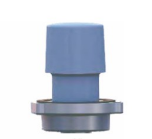
An installed cable terminal, a protected unused socket, and an interface reserved for another accessory are three different conditions. Clear identification prevents an insulation plug from being treated as a generic cap that can move between unlike sockets. When a spare way is later used, its socket size and voltage class still determine which terminal or accessory can be fitted.
The same principle applies to an inner-cone surge arrester. Its configuration depends on the system voltage and protection study as well as the matching interface. We do not treat an empty socket alone as evidence that an arrester belongs there. The protection function and interface fit are both necessary, and neither one proves the other.
Use Standards to Confirm the Product Boundary
The JY NZ terminal page references IEC 60840 and GB/T 12706 for the cable accessory system, together with equipment-related requirements such as GB/T 11022 and DL/T 404. These references help define the product and test framework for the stated voltage class. They do not make every product described as an Inner Cone Connector interchangeable.
Standard references remain attached to the actual product and equipment interface. IEC 60840 addresses extruded-insulated power cables and accessories above 30kV, while the equipment standard and the socket drawing establish other parts of the connection requirement. Utility or regional requirements may add tests, documentation, or installation controls, but they do not change the physical need for a matching socket and terminal.
The word Connector describes a mating electrical interface in a broad sense. At 35kV, the connection also depends on controlled insulation geometry, electric stress management, shielding, grounding, sealing, and mechanical engagement. A standards list cannot compensate for an unverified taper size or cable dimension.
In our product documentation, we connect the applicable standard references to the product model, voltage class, current class, interface size, and relevant test scope. This keeps each standard tied to the Inner Cone Connector configuration it supports instead of turning it into a broad claim about every connector in our range.
We apply those references to each Inner Cone Connector family within its stated product boundary, not as a universal compatibility statement.
Verify the Complete Interface Before Installation
Before installation, the complete interface can be checked as a physical chain from the equipment socket to the supported cable. The important question is not whether every individual part carries a suitable voltage label. It is whether the socket geometry, terminal size, conductor contact, cable adapter, stress-control parts, grounding arrangement, and working space describe one compatible assembly.
Table 2. Final Interface Checks for a 35kV Connection
| Interface area | What we confirm in our product configuration | Why it matters at installation |
|---|---|---|
| Equipment side | Socket drawing, inner-cone size, contact position, flange and mounting arrangement | Establishes the mating geometry for the terminal |
| Electrical rating | System voltage, maximum operating voltage, continuous current and required duty | Keeps the connector within the rating of the complete current path |
| Cable side | Conductor material and construction, cross-section, diameter over insulation and screen design | Defines the conductor contact, adapter and stress-control parts |
| Compartment | Cable entry direction, insertion clearance, bend space, support and maintenance access | Allows full insertion without side load or cable strain |
| Unused interface | Matching insulation plug or approved accessory, grounding and identification | Keeps an empty socket insulated, sealed and clearly distinguished |
| Installation basis | Product drawing, component relationship and installation instruction | Keeps the assembled interface consistent with the verified product design |
During commissioning, the installed Inner Cone Connector model and size need to match the intended equipment position. The cable identification, contact type, adapter or stress-control selection, terminal seating, grounding connection, and mechanical support can then be checked against the product instruction. These checks verify the physical connection; they do not replace qualified high-voltage installation work.
We manufacture the terminal, socket, protective plug, and related inner-cone accessories as defined product families. Our 35kV range keeps the mating size, electrical rating, conductor configuration, and protective accessories connected to the same interface concept. The result is an Inner Cone Connector system in which every component has a specific place in one complete cable connection.
The correct Inner Cone Connector begins with the equipment socket and ends with the installed cable route. Voltage and current ratings define necessary limits, but the socket size, contact position, conductor configuration, insulation diameter, compartment clearance, cable support, and protective treatment of unused ways determine whether the connection can actually be assembled and maintained.
In our JY NZ-35(40.5) family, the 35kV and 40.5kV-class rating belongs to a defined #1, #2, or #3 inner-cone system and a selected 630A or 1250A configuration. We keep those choices connected across the terminal, socket, conductor contact, cable-side parts, and protective accessories. An Inner Cone Connector works as a system only when every mating and cable-side component is selected for the same verified connection.
Frequently Asked Questions
What is an Inner Cone Connector used for
An Inner Cone Connector creates a detachable cable connection to equipment fitted with a matching inner-cone socket. In our 35kV product range, we use this connection concept at cable entries for equipment such as switchgear, ring main units, and prefabricated substations.
Can I select the connector from the 35kV rating alone
No. The 35kV rating identifies the voltage class, but the Inner Cone Connector must also match the socket size, current class, cable conductor, diameter over insulation, and compartment layout.
Are number 1 number 2 and number 3 inner cone sockets interchangeable
No. The size series identifies different mating interfaces and configurations. The terminal, socket, and protective accessories must use the same verified size designation.
Is a 630A terminal suitable for a 1250A equipment position
Not automatically. The complete current path, including the equipment socket, terminal, contact, cable, and equipment rating, must support the required current. A higher equipment-bus rating does not redefine a lower-rated cable interface.
Does 240 mm² identify the correct terminal kit
No. Conductor cross-section is only one input. The final Inner Cone Connector configuration also depends on conductor material and construction, diameter over insulation, insulation type, screen design, and the exact product range.
Can an inner cone plug be removed while the circuit is energized
Do not treat a detachable inner-cone accessory as a loadbreak device. Operation must follow the equipment manual, product instructions, and the approved isolation, verification, grounding, and high-voltage work procedure.
What should be fitted to an unused inner cone socket
Use the insulating protective plug or other approved accessory made for the exact socket size and voltage class. Our matching plug range keeps the unused interface sealed and insulated while the equipment grounding and identification arrangement remains clear.