
In a medium-voltage cable system, choosing between a single-pass and double-pass bushing connector is not simply a matter of selecting one product instead of another.
The bushing structure affects how cables connect to transformers, switchgear, ring main units, cable branch equipment, and other medium-voltage equipment. It also determines how many separable connection interfaces are available at the same equipment position.
At YIEOU, we manufacture Separable Connector systems and related medium-voltage cable accessories for different equipment and cable layouts. When a project requires single-pass or double-pass bushing connectors, we normally start with the electrical connection arrangement rather than the product name alone.
We need to understand how many cable interfaces are required, what each interface will be used for, what equipment is being connected, and whether the project needs an additional connection for another cable, a spare position, grounding, testing, or future expansion.
A single-pass structure is often sufficient when one cable connection is required at the equipment position. A double-pass structure provides another compatible separable interface when two connection points are needed.
The correct choice depends on the actual project layout and how the Separable Connector, equipment interface, cable specification, rated voltage, rated current, and surrounding medium-voltage accessories work together.
What Is the Difference Between Single-Pass and Double-Pass Bushing Connectors?
The most practical difference is the number of separable connection interfaces available at the equipment connection point.
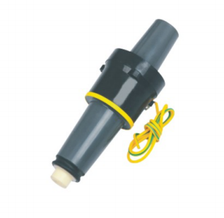
A single-pass bushing connector generally provides one usable interface for a cable connection.
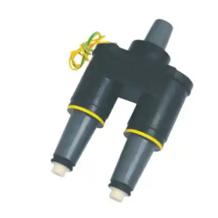
A double-pass bushing connector provides two usable interfaces, allowing another compatible connector or accessory to be connected at the same position.
For example, if a transformer only needs one incoming cable connection on each phase, a single-pass configuration may be sufficient.
If one cable enters the equipment and another cable needs to continue toward the next transformer, switchgear section, or distribution point, the project may require a double-pass arrangement.
The decision therefore starts with the function of each cable connection rather than simply choosing the structure with more interfaces.
A Single-Pass Structure Is Suitable When Only One Cable Interface Is Needed
A single-pass configuration is usually the more straightforward option when one cable needs to connect to one equipment interface.
Typical situations include:
- one incoming cable feeding a transformer;
- radial distribution arrangements;
- equipment positions without a downstream cable connection;
- installations where branching is handled at another point;
- projects without a planned second connection at the same interface.
In this type of arrangement, the Separable Connector connects the prepared medium-voltage cable to the compatible equipment-side interface.
For a 200A loadbreak system, for example, the elbow connector needs to match the corresponding loadbreak bushing interface. The voltage class, current rating, cable conductor size, cable insulation diameter, contact system, and interface structure should all be confirmed together.
If only one interface is required, adding a second one does not automatically improve the installation.
An unused energized interface still needs to be properly insulated and protected, so the second connection point should have a clear project purpose.
When Does a Double-Pass Bushing Connector Make More Sense?
A double-pass structure becomes useful when two compatible separable connection interfaces are required at the same equipment position.
One common situation is a distribution network where one cable reaches the equipment and another cable continues toward the next section of the system.
It can also be considered when a project intentionally reserves another connection point for future expansion or another planned accessory.
Before confirming a double-pass configuration, several points should be clear:
- Where does the first cable come from?
- Where does the second cable go?
- Will both interfaces be used during normal operation?
- Is one interface intended as a spare?
- Will either interface be used for grounding or testing?
- Is future expansion already included in the project design?
- What type of connector will be installed on each interface?
These details affect not only the bushing connector but also the complete Separable Connector and accessory configuration.
Double-Pass Does Not Automatically Mean Loop Feed
Double-pass bushing connectors are often associated with loop-feed applications, but the two concepts should not be treated as the same thing.
A double-pass bushing connector describes the physical availability of two compatible separable interfaces.
A loop-feed system describes how the medium-voltage distribution network is electrically arranged.
Loop-feed projects often require multiple cable connection points, so double-pass or other multi-interface components may naturally be used. However, two physical interfaces alone do not define the complete network topology.
The connection may also involve additional bushings, junctions, switchgear functions, protection equipment, or internal equipment connections.
For this reason, a single-line diagram or connection drawing is much more useful than relying only on terms such as “radial feed” or “loop feed.”
The drawing shows which cable is incoming, which cable is outgoing, which interfaces are active, and whether any position needs to remain available for future use.
Confirm the Number of Interfaces Before Finalizing the Accessories
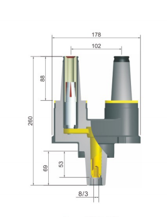
Changing from a single-pass to a double-pass structure can also change the accessory list.
Depending on the project, the complete connection may include:
- loadbreak elbow connectors;
- bushing inserts;
- equipment bushings;
- single-pass or double-pass bushing connectors;
- insulated caps;
- grounding elbows;
- junctions;
- surge arresters;
- parking or standoff accessories.
Not every project needs every component.
The accessory combination should follow the actual electrical layout.
For example, if a double-pass connector has one operating cable connection and one unused interface, the spare interface cannot simply remain open.
It needs a compatible insulating and shielding solution before the system is energized.
If the spare interface is intended for future expansion, it is also worth confirming the planned cable and connector system at the beginning of the project. This makes future connection work easier and avoids unnecessary changes to the equipment-side interface.
Voltage Rating Alone Is Not Enough to Match a Separable Connector System
System voltage is one of the first parameters to confirm, but it cannot determine the complete connector configuration on its own.
Two products may belong to the same general voltage class and still use different interfaces, current ratings, cable ranges, or connection structures.
For a complete match, the following information should normally be considered together:
| Project information | What needs to be confirmed |
| System voltage | Required insulation class |
| Rated current | Connector system and current requirement |
| Single-pass or double-pass requirement | Number of equipment-side interfaces |
| Equipment type | Installation and connection structure |
| Bushing/interface type | Mechanical and electrical compatibility |
| Cable conductor size | Contact and conductor connection range |
| Cable insulation diameter | Connector body and sealing range |
| Cable construction | Cable preparation and accessory matching |
| Number of cables | Required connection arrangement |
| Network drawing | Function of each connection point |
| Spare interface requirement | Need for insulating accessories |
| Grounding arrangement | Grounding and shielding configuration |
For separable connector systems, interface compatibility is especially important.
The connector body, equipment-side component, contact system, and cable dimensions need to work as one compatible assembly.
This is why cable data and equipment interface information should ideally be provided together when the project accessories are being confirmed.
The Bushing Connector Must Match the Separable Connector Interface
The cable connector and equipment-side component form one complete electrical interface.
They should not be selected independently.
In a typical 200A loadbreak system, for example, the elbow connector needs to mate with the corresponding 200A loadbreak interface.
The same principle applies whether the equipment uses a single-pass or double-pass structure.
The additional interface on a double-pass connector is not simply another physical opening. It must provide the correct mating interface for the intended Separable Connector or accessory.
The complete connection needs to maintain:
- reliable electrical contact;
- insulation performance;
- electric-field control;
- mechanical stability;
- external shielding;
- environmental sealing.
When several connector and bushing components are used in the same project, checking them as one system helps avoid interface mismatches between independently selected accessories.
Cable Size Still Needs to Be Confirmed After Choosing Single-Pass or Double-Pass
Selecting the equipment-side structure does not complete the connector selection.
The medium-voltage cable still needs to match the Separable Connector.
Two projects can use the same single-pass or double-pass bushing arrangement while requiring different elbow or connector specifications because the cable dimensions are different.
The conductor cross-section affects the conductor contact or compression connection.
The cable insulation diameter affects the fit of the molded connector body, stress-control area, and sealing section.
Cable construction can also affect preparation and accessory selection.
This becomes particularly important when cables, transformers, switchgear, and cable accessories are purchased from different suppliers.
In that situation, both the equipment interface information and cable datasheet should be checked before the connector configuration is finalized.
Spare Interfaces Need Proper Insulation and Protection
Some projects choose a double-pass structure because one connection point will be reserved for future expansion.
That can be practical, but the unused interface still needs to be handled correctly.
An unused energized separable interface should not remain exposed.
A compatible insulating cap or other suitable insulating accessory should be installed according to the connector system.
The spare interface should therefore be included in the original project accessory list.
For example, if several transformers each have one reserved interface, the required insulating caps should be ordered together with the main connectors.
It is a small detail during procurement, but an important one when the system reaches installation and commissioning.
A Connection Drawing Makes the Structure Easier to Confirm
For projects with several cable connection points, a simple drawing can provide the required information more clearly than a long product description.
The drawing should ideally show:
- transformer, RMU, or switchgear position;
- incoming cables;
- outgoing cables;
- number of connection points per phase;
- intended single-pass or double-pass structure;
- cable destinations;
- spare interfaces;
- grounding or surge-protection accessories where required.
If the equipment supplier has already provided an interface designation or dimensional drawing, that information should also be included.
For replacement projects, photos can help identify the existing arrangement, but appearance alone may not always be enough to confirm compatibility.
Different medium-voltage cable accessories can have similar external shapes while using different mating interfaces or dimensional structures.
When the existing interface cannot be identified confidently, dimensions and equipment information should be checked before the replacement connector is confirmed.
Manufacturing Consistency Matters Across the Complete Connection System
A Separable Connector Manufacturer needs to control more than the external shape of the product.
A separable connector system combines molded insulation, conductive or semiconductive shielding layers, metallic current-carrying components, stress-control structures, mating interfaces, and sealing surfaces.
These parts need consistent dimensions and material performance so that the components can be assembled correctly in the field.
This becomes especially important when several interfaces are used at the same equipment position.
In a double-pass configuration, multiple connectors or accessories may need to mate with the same bushing assembly. The dimensional relationship between each interface therefore needs to remain consistent.
For project orders, the important relationships include:
- connector body and cable range;
- contact component and conductor size;
- connector and bushing interface;
- single-pass or double-pass equipment structure;
- insulating accessories and spare interfaces;
- grounding accessories and external shielding.
The purpose is to keep the components used in one project within the same compatible connection system.
How Do We Decide Between Single-Pass and Double-Pass?
In many projects, the decision can start with three practical questions.
Does This Position Need Only One Cable Connection?
If one cable connects to the equipment and there is no requirement for a second interface, a single-pass structure is usually the more direct option.
There is little reason to add another connection point unless the electrical layout or future expansion plan requires it.
Does Another Cable Need to Continue from the Same Position?
If the equipment position requires one incoming and one outgoing cable interface, a double-pass structure may be suitable.
The function of both cables and the complete network arrangement should still be confirmed before the configuration is finalized.
Will One Interface Be Reserved for Future Use?
If one interface will remain unused initially, the future connection plan and the required insulating accessory should be considered together.
This allows the current installation and future expansion to use a consistent interface arrangement.
Matching the Complete Separable Connector System at YIEOU
At YIEOU, we do not look at the single-pass or double-pass bushing connector as an isolated item.
When you send us a project requirement, we can review the equipment type, electrical layout, cable specification, and required connection points together.
Typical information includes:
- operating voltage;
- rated current;
- equipment-side interface;
- single-pass or double-pass requirement;
- number of cable connections;
- cable conductor size;
- cable insulation diameter;
- connector type;
- spare interface requirements;
- grounding and related accessories.
If a double-pass arrangement is required, we also confirm what each interface will be used for.
After the connection points are clear, the Separable Connector, bushing components, insulating accessories, grounding accessories, and other required medium-voltage cable accessories can be matched around the same project configuration.
For repeat or batch projects, a confirmed configuration also makes it easier to maintain consistent interfaces and accessory combinations across multiple transformers, RMUs, or switchgear positions.
Choose the Bushing Structure from the Actual Project Layout
Single-pass and double-pass bushing connectors are designed for different connection requirements.
A single-pass structure is generally suitable when one separable cable interface is required at the equipment position.
A double-pass structure is useful when two compatible interfaces are required at the same position.
Neither structure is automatically better.
The right choice depends on how the cables, equipment, and accessories are arranged in the actual medium-voltage distribution system.
At YIEOU, we manufacture Separable Connector systems and related medium-voltage cable accessories for different project layouts. If you are not sure whether your application requires a single-pass or double-pass structure, send us the single-line diagram, equipment interface information, cable specification, rated voltage, rated current, and intended function of each connection point.
We can then match the bushing structure, Separable Connector, and surrounding accessories around the actual project connection instead of selecting each component separately.
FAQ
What is the main difference between a single-pass and double-pass bushing connector?
A single-pass structure generally provides one separable connection interface, while a double-pass structure provides two. The final choice depends on the equipment and cable layout.
Does a loop-feed system always require a double-pass bushing connector?
No. Loop feed describes the electrical network arrangement, while double-pass describes the number of available connection interfaces. The single-line diagram should be checked before the structure is confirmed.
Can one interface of a double-pass connector remain unused?
Yes, if the project is designed that way, but the unused energized interface needs a compatible insulating accessory before the system is put into service.
What information should I send when ordering Separable Connectors?
Send the system voltage, rated current, cable conductor size, cable insulation diameter, equipment interface, number of cable connections, and preferably a connection drawing or single-line diagram.
Can the same Separable Connector be used with both single-pass and double-pass bushings?
It may be possible if both structures use the same compatible mating interface. The voltage class, current rating, cable range, and interface type still need to be confirmed.
Is a double-pass structure better for future expansion?
It can be useful when a second connection is already part of the future project plan. If no additional connection is expected, adding an unused interface may only increase the accessory requirements.