
Pad-mounted transformers are widely used where medium-voltage underground cables need a protected and compact connection to the distribution transformer. Unlike an exposed overhead connection, the primary cable interface is normally enclosed inside the transformer compartment, where the cable, bushing and connector must work together as one complete system.
For this reason, choosing a Separable Connector for a pad-mounted transformer should not begin with the connector model alone.
The transformer bushing interface, system voltage, current requirement, cable dimensions, operating method and cable layout all affect the final choice. A connector with the correct voltage marking can still be unsuitable if its interface or cable range does not match the transformer installation.
At YIEOU, we manufacture medium-voltage cable accessories for transformers, switchgear, RMUs, cable branch equipment and other distribution applications. For pad-mounted transformer projects, we normally look at the transformer side and cable side together before confirming the connector configuration.
Why Are Separable Connectors Commonly Used on Pad-Mounted Transformers?
A pad-mounted transformer supplied by underground medium-voltage cables needs a reliable way to connect those cables to the transformer primary bushings.
A Separable Connector creates an insulated and screened connection between the cable and the equipment interface. Depending on the system design, the connector can also support maintenance, isolation, testing, grounding, surge protection or future cable changes.
This is particularly useful for pad-mounted equipment because connection space is limited and the primary compartment needs to remain organized.
The connection is more than an elbow
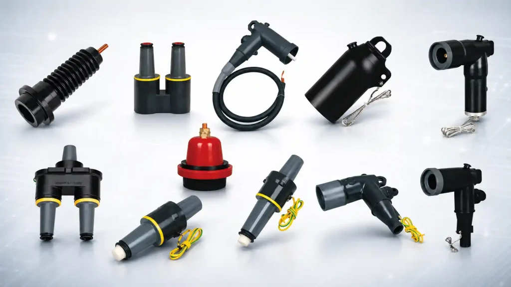
A typical 200A transformer cable connection may involve:
- an equipment bushing well;
- a bushing insert;
- a loadbreak elbow connector;
- a cable contact and cable adapter;
- grounding and shielding components.
Higher-current transformer circuits may instead use a 600A-class deadbreak connection and a different equipment interface.
These components should therefore be selected as a system rather than purchased separately based only on their external appearance.
Start With the Transformer Bushing Interface
The first question should usually be:
What interface is already installed on the transformer?
The transformer determines the equipment side of the connection. Once the bushing type is fixed, the range of compatible Separable Connector options becomes much narrower.
Trying to select the cable connector first and adapt the transformer afterward can create unnecessary problems.
Identify the equipment interface
For a new pad-mounted transformer, check the transformer drawing and bushing specification.
For an existing transformer, the original documentation, equipment markings and dimensions should be reviewed whenever possible.
Do not rely only on photographs.
Two medium-voltage bushings can look similar while using different interface dimensions or operating structures. A connector should not be forced onto an interface simply because the rated voltage appears correct.
Bushing wells and bushing inserts
In a typical 200A loadbreak arrangement, the transformer may use a bushing well together with a removable bushing insert.
The bushing insert then provides the mating interface for the elbow connector.
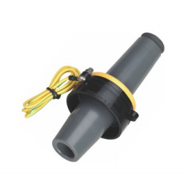
For example, YIEOU’s JY DTT-15/200 15kV 200A Bushing Insert is designed to thread into a suitable bushing well and work with a corresponding 200A loadbreak connection. Its rated voltage is 15kV, with a maximum operating voltage of 17.5kV, and its rated current is 200A.
This illustrates an important selection principle:
the bushing well, insert and elbow must belong to the same compatible connection system.
Should the Transformer Use a 200A or 600A Connection?
Current rating is one of the most visible differences between transformer connector systems, but it should not be treated as a simple choice between a “small” and a “large” connector.
The required interface depends on the transformer design, feeder arrangement and expected current.
| Connection Class | Typical Current Rating | Common Operating Structure |
|---|---|---|
| Loadbreak system | 200A | Loadbreak elbow |
| Higher-current system | 600A class | Commonly deadbreak |
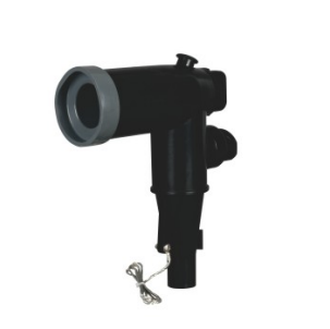
| YIEOU JY ZT-15/200 | 200A | 15kV loadbreak elbow |
| YIEOU JY DTT-15/200 | 200A | 15kV bushing insert |
A 200A system can be appropriate where the transformer and feeder are designed around a 200A loadbreak interface.
For example, the YIEOU JY ZT-15/200 15kV 200A Loadbreak Elbow Connector is designed for underground medium-voltage cable connections to compatible distribution equipment. It is rated at 15kV and 200A and is intended to work with a matching loadbreak interface.
A 600A-class connection is used where the equipment and circuit require a higher-current interface. YIEOU’s existing 600A Separable Connector systems are commonly configured as deadbreak connections for transformers and other medium-voltage equipment.
Do not replace the equipment rating with an assumption
A large transformer does not automatically mean that a particular 600A connector model should be selected.
Likewise, a 200A elbow should not be selected merely because it is commonly seen on pad-mounted transformers.
The transformer bushing specification and circuit current requirement must confirm the interface.
For replacement projects, matching the original interface is especially important.
Match the Connector to the System Voltage
The next step is to confirm the voltage class.
The connector, transformer bushing and cable insulation system must all be suitable for the same application.
A 15kV-class product should not be selected for another voltage class simply because its physical dimensions appear similar.
At YIEOU, for example, our 15kV 200A product range includes loadbreak elbows and bushing inserts intended to operate together. We also manufacture medium-voltage accessories for other voltage classes and connection arrangements.
Check more than the printed voltage
When evaluating voltage compatibility, engineers and buyers should consider:
- system rated voltage;
- maximum operating voltage;
- equipment insulation requirements;
- connector insulation level;
- bushing interface;
- related accessories in the same connection system.
The goal is not to find the connector with the highest voltage number.
The goal is to build a coordinated insulation system between the cable and transformer.
This matters particularly in underground distribution networks, where a connection may remain in service for years without frequent physical inspection.
Cable Size Alone Is Not Enough to Select the Connector
The transformer interface determines one side of the Separable Connector. The cable determines the other.
This is where many replacement and procurement projects become more complicated.
A buyer may know that the cable is, for example, 70mm² or 120mm². That information is useful, but conductor cross-sectional area alone does not completely define the cable interface.
Check the conductor
The cable contact must match the conductor.
Important factors include:
- conductor cross-sectional area;
- copper or aluminium conductor;
- conductor construction;
- applicable cable lug or contact.
Incorrect conductor matching can affect crimping and electrical contact.
Check the diameter over insulation
This is especially important for a Separable Connector.
Two cables with the same conductor cross-section can have different insulation dimensions because cable constructions and manufacturers vary.
The connector body and cable adapter therefore need to match the actual cable insulation diameter.
For this reason, we do not recommend identifying a complete connector kit from conductor size alone when the actual cable construction is uncertain.
Check the complete cable specification
Cable information should be reviewed together with the transformer connection.
The insulation system, screen structure and dimensional data influence how the cable is prepared and how the connector fits.
For a new project, cable technical data can normally be checked before accessory production.
For a replacement project, the actual installed cable should be identified carefully rather than assuming that every cable of the same nominal size is identical.
Loadbreak or Deadbreak Depends on How the Connection Will Operate
The operating method is another major difference between Separable Connector systems.
200A loadbreak connections
A compatible loadbreak elbow and bushing system is designed for specified loadbreak operation under the conditions defined for that product and system.
This does not mean the connector can simply be disconnected whenever convenient.
Medium-voltage operating procedures, suitable equipment and trained personnel remain essential.
For pad-mounted transformers using a compatible 200A system, a loadbreak elbow can provide a practical removable cable interface.
Deadbreak connections
A deadbreak connector is not intended to be disconnected while carrying load current.
Higher-current 600A-class systems commonly use this arrangement.
For a pad-mounted transformer with a higher-current primary connection, this type of structure may provide the required cable-to-transformer interface, but the system must be isolated before the connection is separated.
The correct choice therefore depends on the transformer and network operating design rather than a preference for one connector shape.
Consider Whether the Transformer Uses Radial or Loop Feed
Pad-mounted transformer layout also affects the accessory configuration.
A transformer may have a relatively simple radial arrangement, or it may form part of a looped underground distribution system.
These layouts can create different requirements for bushings, cable paths and additional interfaces.
Radial arrangements
In a straightforward radial arrangement, the cable enters the transformer and supplies that transformer connection point.
The accessory layout can therefore remain relatively simple when the transformer bushing and cable specification are already clear.
Loop-feed arrangements
A loop-feed configuration may require additional connection points so that the distribution circuit can continue toward another transformer or network section.
This is where the surrounding medium-voltage cable accessories become important.
Depending on the transformer and network design, the system may use additional bushing interfaces, junctions, pass-through arrangements or other compatible accessories.
YIEOU also manufactures single-pass and double-pass bushing connection products for projects requiring different numbers of separable interfaces.
The number of interfaces should therefore be confirmed from the electrical layout rather than assuming that every pad-mounted transformer uses the same arrangement.
Leave Enough Space for the Cable and Connector
Electrical compatibility does not automatically mean that the installation will be practical.
A pad-mounted transformer compartment has physical limits.
Cable entry position, bending radius, phase spacing and access for installation all influence connector selection.
Cable direction matters
The elbow or deadbreak connector changes the direction in which the cable approaches the transformer interface.
If the cable trench and transformer bushing positions are not coordinated, installers may be forced to bend the cable more tightly than planned.
The connector layout should therefore be reviewed together with the cable entry path.
Do not ignore installation clearance
The installer needs enough room to:
- prepare the cable;
- install the contact;
- position the connector;
- connect grounding components;
- access the interface during maintenance.
This is particularly important when several medium-voltage cables enter the same transformer compartment.
The most compact-looking connector arrangement is not necessarily the easiest one to install.
Think About Grounding, Surge Protection and Spare Interfaces
The main cable connection is only part of the transformer accessory system.
Some pad-mounted transformer projects also require additional functions around the primary cable interface.
Grounding
Grounding components should be coordinated with the connector and the maintenance procedure.
Where temporary grounding is required, a compatible grounding arrangement should be planned instead of improvised after installation.
Surge protection
A transformer connected to an underground medium-voltage network may also require surge protection according to the system design.
If a separable surge arrester is used, its electrical rating and interface must match the connection system.
Physical fit alone does not confirm that a surge arrester is suitable.
Spare interfaces
Some transformer or loop-feed arrangements include an unused or reserved connection position.
An energized spare interface should not simply be left exposed.
A compatible insulating cap or other specified protective accessory should be included in the original accessory plan.
This is a small component, but it is much easier to specify it during procurement than to discover the omission during commissioning.
How YIEOU Approaches Pad-Mounted Transformer Connector Selection
For us, choosing a Separable Connector for a pad-mounted transformer is not simply a matter of searching for a model with the correct voltage.
The complete connection needs to make sense from the transformer bushing to the cable.
A typical selection starts with the transformer interface. We then check the voltage and current class, cable conductor, actual cable dimensions, required operating function and physical connection layout.
For a 15kV 200A transformer connection, for example, a system may use a JY DTT-15/200 Bushing Insert together with a compatible JY ZT-15/200 Loadbreak Elbow Connector. Both components belong to the 15kV 200A connection arrangement, but the final connector configuration still depends on the actual transformer and cable.
For other transformer interfaces or higher-current circuits, the accessory structure may be different.
This is why we prefer to match medium-voltage cable accessories around the actual equipment connection rather than treat each component as an independent product.
Conclusion
Choosing a Separable Connector for a pad-mounted transformer starts at the transformer interface.
The connector must match the equipment bushing, system voltage, required current, cable conductor and actual cable dimensions. The operating structure also matters: a 200A loadbreak system and a 600A-class deadbreak system serve different connection requirements and should not be treated as interchangeable simply because both are used on medium-voltage transformers.
The surrounding layout should also be considered. Radial or loop-feed arrangements, cable entry direction, available compartment space, grounding, surge protection and spare interfaces can all affect the final accessory combination.
YIEOU manufactures Separable Connector systems and related medium-voltage cable accessories for transformer and distribution applications. By matching the connector, bushing and cable as a complete interface, we can support more practical installation and more consistent cable connections for pad-mounted transformer projects.
FAQ
Can a 200A loadbreak elbow be used on every pad-mounted transformer?
No. A 200A loadbreak elbow requires a compatible transformer interface and electrical rating. The transformer bushing specification should be checked before the elbow connector is selected.
Is a 600A Separable Connector always better than a 200A connector?
No. The two systems are intended for different current requirements and interface structures. A higher current rating does not make a connector more suitable if the transformer is designed around another interface.
Can I select a Separable Connector only from the cable cross-section?
No. Conductor size is only one part of the selection. The conductor material, cable construction and actual diameter over insulation also need to match the connector components.
Why does the transformer bushing need to be checked before ordering the connector?
The bushing defines the equipment-side mating interface. If the connector and bushing are from incompatible interface systems, correct installation cannot be confirmed even when their voltage and current labels appear similar.
Can the same pad-mounted transformer use both cable connection and surge-protection accessories?
Yes, when the transformer and network layout provide compatible interfaces for those functions. The surge-protection accessory must be selected according to the electrical requirements and the interface of the complete connection system.