
Switchgear can pass through several different test stages before and after it enters service. A production team may need a high-voltage connection for factory testing, a commissioning team may need to confirm phase relationships, and an operator may want a visible indication associated with an energized cable circuit. These activities sound similar because they all involve voltage, yet they do not use the same accessory or the same interface. When a Separable Connector system is specified, the testing purpose must be identified before the connector, test point, indicator, or temporary test terminal is selected.
Quick Answer
A capacitive test point on a Separable Connector is a sensing interface intended for a compatible voltage indicator, phase-comparison device, or fault indicator when the Separable Connector design supports it. It is not the same as a detachable test terminal that connects high-voltage test equipment directly to an equipment bushing for withstand or partial-discharge testing.
At YIEOU, we manufacture medium-voltage cable accessories for several interface systems. We first confirm what needs to be tested, where the connection will be made, and whether the project uses a 200A loadbreak elbow, a 600A deadbreak connector, or a 630A European-style external-cone bushing. That distinction keeps a useful indication feature from being mistaken for a high-voltage test connection.

Start With the Test Purpose Rather Than the Accessory Name
The word test can refer to very different tasks. A maintenance team may want to identify whether a circuit is energized. A commissioning team may need phase comparison between two connection points. A fault indicator may use the electric field around an energized cable to help identify a faulted section. A switchgear manufacturer may need to apply a specified test voltage to an external-cone bushing before a cable termination is installed.
These tasks differ in energy, connection method, equipment, and procedure. The Separable Connector and its accessory system should therefore be matched to the intended test rather than selected because a product description happens to mention a test point.
A useful project discussion begins with four questions. What test or indication is required? Which component will remain installed during normal service? What equipment interface is available at the test location? Which approved instrument or test lead must connect to it? The answers determine whether the project needs a Separable Connector with a capacitive test point, a separate indicator, a test adapter, or a dedicated external-cone test terminal.
This distinction also affects purchasing. A Separable Connector body, test-point cap, indicator, and high-voltage test terminal are not interchangeable line items. Treating them as one generic testing accessory can result in a kit that fits the cable but cannot support the intended commissioning or operating task.
Our Separable Connector range includes American-style loadbreak and deadbreak products in which test-point availability depends on the specific design. We review that feature alongside the voltage class, current class, equipment interface, cable construction, and operating method.
A Capacitive Test Point Is a Sensing Interface
A capacitive test point obtains a small coupled signal from the energized conductor through the insulation structure. A compatible instrument can use that signal for an intended indication or comparison function. The test point does not carry the main load current, and it does not expose the primary conductor as a conventional electrical terminal.
The practical value is accessibility. The sensing location is built into the Separable Connector body, so the correct device can be applied without dismantling the main cable connection. This can support voltage indication, phase identification, or a compatible fault-indication arrangement, depending on the product and instrument.
The wording matters. A voltage indication is not automatically the same as an absence-of-voltage test for work. The Separable Connector manufacturer’s instructions, the instrument rating, the equipment owner’s procedure, and the applicable safety rules determine how the indication may be used. A reading from a test point should not be treated as permission to touch, disconnect, or ground the circuit.
That limitation is especially important when a result appears to show no voltage. The instrument may be unsuitable for the test point, incorrectly connected, damaged, or affected by the condition of its reference path. Approved isolation and verification procedures remain necessary. In practice, the Separable Connector test point is one defined source of information within that procedure, not a replacement for the procedure itself.
The cap over the test point also belongs to the product system. It protects the sensing interface during normal service and should remain matched to the Separable Connector design. Losing the cap or replacing it with an unrelated cover changes the condition of the connector and should be resolved according to the product instructions.
Test Point Availability Depends on the Connector Design
Two Separable Connector products in the same broad category may not provide the same sensing feature. The feature can be standard, optional, or absent. Its position and compatible instruments can also differ. For that reason, a request such as “include a test point” needs to identify the exact Separable Connector model and the device expected to use it.
For a 15kV 200A loadbreak application, our JY ZT-15/200 elbow incorporates a capacitive voltage-divider structure for live indication. Its delivery scope includes a test-point cap. The elbow remains a cable termination for a compatible 200A loadbreak interface; the sensing feature does not change the interface family or remove the operating conditions that govern loadbreak work.
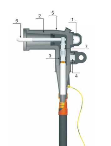
The JY ZT-25/200A loadbreak elbow provides another example. Its official product information identifies an optional capacitive test point for use with fault indicators. The presence of a similar-looking boss on an elbow is not enough to confirm that the option was supplied or that any indicator will work with it. The actual configuration and compatible indicator need to be confirmed in the order.
This is one reason photographs alone are weak procurement evidence. The external shape may remain similar across voltage classes or options while the internal insulation, probe, cable range, and test-point provision differ. A Separable Connector should be identified from its model, interface data, and supplied configuration rather than from the outline of the rubber body.
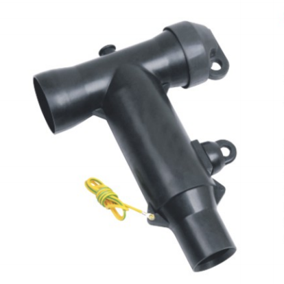
The same principle applies to 600A deadbreak systems. Our JY TT-600 product information describes an optional capacitive test point similar in purpose to those used on 200A elbow connectors, including use with fault indicators. It remains a 15kV or 24kV class 600A deadbreak cable termination for compatible apparatus. The option does not give the Separable Connector a loadbreak function.
A High Voltage Test Terminal Carries a Different Test Connection
A dedicated test terminal has another purpose. Instead of sensing a coupled voltage at an installed cable connector, it creates a temporary insulated connection between test equipment and an equipment bushing. The component becomes part of the high-voltage test circuit for the specified factory, handover, or preventive test.
Our JY SYZD-15/24/630 test terminal is designed for the external conical bushing of 15kV and 24kV, 630A European-style switchgear. It can connect the bushing to high-voltage test equipment for activities such as power-frequency withstand and partial-discharge testing without installing a cable connector for the test. This is useful when a switchgear manufacturer needs to test the equipment interface before the project cable assembly is available.
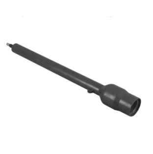
The long insulated body and high-voltage connection point reflect this different role. It is not a cap for a capacitive sensing point, and it is not inserted into the small test-point feature on a loadbreak elbow. It mates with the specified external-cone bushing interface. The test lead, grounding arrangement, test voltage, and operating sequence belong to the approved test setup.
The JY SYZD-35/630 follows the same general product purpose for a 35kV, 630A European-style external-cone bushing, but it is a different voltage and interface application. Its existence does not make a 15/24kV terminal suitable for 35kV equipment. The bushing interface, insulation class, and test requirements must agree with the selected terminal.
The difference can be summarized by the electrical path. A capacitive test point senses a scaled signal through the Separable Connector insulation. A high-voltage test terminal intentionally connects the test source to the equipment interface. Similar words do not make those two paths equivalent.
Table 1. Capacitive test point and test terminal comparison
| Selection question | Capacitive test point on a Separable Connector | Dedicated external-cone test terminal |
|---|---|---|
| Main purpose | Voltage indication, phase comparison, or compatible fault indication | Connection of specified high-voltage test equipment to a bushing |
| Normal location | Built into an installed Separable Connector body | Temporarily installed on a compatible equipment bushing |
| Electrical relationship | Coupled sensing signal through insulation | Conductive high-voltage test path |
| Typical interface examples | Optional or integrated point on 200A loadbreak or 600A deadbreak products | 15/24kV or 35kV 630A European-style external-cone bushing |
| What must be matched | Connector design, test-point option, indicator, and procedure | Bushing interface, voltage class, test equipment, and test procedure |
| What it does not prove | It does not by itself establish an electrically safe work condition | It is not a permanent cable connector or normal operating accessory |
Interface Family Comes Before Test Function
Testing requirements do not override interface compatibility. A 200A loadbreak elbow, a 600A deadbreak T connector, and a 630A European-style external-cone system use different mating structures. Even if all three include a feature described with the word test, the components cannot be moved between those systems on that basis.
The 200A elbow example connects a cable to a compatible loadbreak bushing interface. Its capacitive point is integrated into the Separable Connector body. The 600A deadbreak example belongs to a higher-current American-style system and is operated only under the specified de-energized conditions. The 630A test-terminal example connects test equipment to a European-style external conical bushing. These products solve different connection problems.
Voltage class alone cannot resolve the match. A 24kV marking on two products does not show that their contact geometry, external cone, probe, insulation interface, or current class is the same. A Connector works only when its intended mating and electrical relationships are preserved, and medium-voltage accessories add insulation and stress-control requirements to that relationship.
The test instrument must also be considered part of the interface. A capacitive point requires an instrument designed for that point and its intended function. A high-voltage test terminal requires test equipment and leads appropriate to the specified test. Using a familiar instrument on an unfamiliar interface can produce misleading information or place the assembly outside its intended duty.
We therefore keep three records together during product matching: the equipment bushing drawing, the Separable Connector or test-terminal model, and the intended test equipment. This makes it easier to see whether the proposed components share a real interface rather than only a voltage label.
Plan Test Access Before the Equipment Layout Is Final
Testing is easier when the required access is considered while the switchgear or transformer compartment is still being designed. A test point that is hidden behind another phase may be difficult to reach with the intended indicator. A bushing that is too close to a barrier may accept its normal cable termination but leave insufficient space for a long temporary test terminal and its lead.
The installed envelope and the test envelope are not always the same. A Separable Connector can fit during normal service while the device used for phase comparison requires a different approach. A temporary test terminal may extend much farther from the equipment face than the cable-side Separable Connector that will eventually replace it. Clearances, barriers, neighboring phases, and the route of the test lead all affect practical access.
The component sequence also matters. Factory testing may occur before cable accessories are fitted. Site handover testing may take place after the equipment is installed but before the final cable connection is complete. Preventive testing may require an outage, removal of an existing accessory, inspection of the bushing, and restoration of the normal connection. The selected product should fit the stage in which it will actually be used.
This planning does not require the Separable Connector manufacturer to design the whole test program. It requires enough information to confirm the correct accessory and working envelope. For OEM projects, an equipment section drawing and the proposed test arrangement are usually more useful than a product name alone.
Where a built-in test point is required for routine indication, it should be included in the ordered Separable Connector configuration. Adding an external high-voltage test terminal later will not create that everyday indication feature. Conversely, ordering a Separable Connector with a test point will not provide the conductive test connection needed for specified withstand testing of an external-cone bushing.
Treat Indication, Verification, and Withstand Testing as Separate Decisions
A clear specification assigns one purpose to each item. Indication helps the operator understand an energized state or phase relationship through an approved device. Verification of de-energization follows the applicable electrical safety procedure and uses the required test equipment. Withstand or partial-discharge testing applies a defined test condition to equipment or insulation through a suitable connection.
Confusing these decisions creates two common errors. The first is expecting a small capacitive point to accept test voltage or primary test current. The second is treating the absence of an indication as complete proof that the circuit is safe for work. Both errors arise from giving the accessory more authority than its design provides.
The correct boundary is practical. The Separable Connector test point provides the signal it was designed to provide. The compatible instrument interprets that signal for its intended purpose. The operating procedure determines what further isolation, voltage verification, grounding, or testing is required. Each part contributes without replacing the others.
A high-voltage test terminal follows a similar boundary. It provides the compatible physical and electrical path between the test set and bushing. It does not determine the correct test voltage, duration, acceptance criteria, or safety controls. Those conditions come from the equipment specification, applicable standards, test plan, and qualified testing team.
This separation also makes maintenance records clearer. The record can identify whether a result came from a capacitive indication point, a direct test connection, or another instrument location. Future teams can then understand what was actually measured instead of treating every voltage-related observation as the same test.
Order the Testing Features With the Complete Connection System
The most useful ordering information connects the test requirement to the actual cable and equipment interface. For a cable-side Separable Connector, the voltage class, current class, loadbreak or deadbreak duty, bushing interface, conductor details, insulation diameter, and required test-point option all matter. The indicator or fault-indication device should be identified as well.
For an external-cone test terminal, the equipment bushing drawing, system voltage, current-class interface, planned test type, test-equipment connection, and required working space are more relevant than cable size. The terminal is being matched to the equipment interface rather than to a project cable.
Table 2. Information that helps us match the testing accessory
| Project information | Why it matters |
|---|---|
| Required indication or test | Separates sensing, phase comparison, fault indication, and high-voltage testing |
| Equipment bushing drawing | Identifies the real mating interface and available space |
| Connector model and option list | Confirms whether a capacitive test point is integrated, optional, or absent |
| System voltage and current class | Narrows the correct product family without assuming interchangeability |
| Intended instrument or test set | Confirms the connection method and accessory compatibility |
| Test stage and compartment drawing | Shows whether access is needed in the factory, during handover, or after installation |
| Local operating and safety procedure | Establishes how indication and verification will be used in practice |
Providing this information helps us match our Separable Connector and test-accessory options to the project. It also helps identify when the request belongs to an American-style cable connector and when it belongs to a European-style equipment-bushing test terminal.
The final specification should name each component separately. For example, a 600A deadbreak connector with an optional capacitive test point is different from a 15/24kV 630A external-cone test terminal. Clear descriptions reduce the chance that an indication feature, cap, adapter, or test connection is omitted from the supplied system.
Keep the Test Feature Proportional to the Real Need
A test feature is valuable when it supports a defined task. Adding one without a compatible instrument or procedure does not improve the installation by itself. The same is true of a test terminal purchased without confirming the bushing interface or test setup.
For recurring switchgear production, a reusable test terminal may simplify the connection between a defined bushing family and the factory test set. For an installed cable circuit, a connector test point may support the operator’s chosen indication or fault-location arrangement. The value comes from repeated compatibility between the accessory, interface, instrument, and procedure.
At YIEOU, we match these products as parts of a medium-voltage connection system. We do not treat every Separable Connector test feature as equivalent. Confirming the test purpose early gives the project the right interface during manufacturing, commissioning, and later service without turning the connector article into a general high-voltage testing manual.
FAQ
Is a capacitive test point a direct connection to the conductor
No. It provides a coupled sensing signal through the connector insulation for a compatible device. It is different from a conductive high-voltage test connection.
Can a no voltage indication prove that a circuit is safe to touch
No. The indication must be interpreted within the applicable isolation and voltage-verification procedure. A compatible test-point instrument does not replace the required safety steps or approved test equipment.
Do all Separable Connector products include a test point
No. Availability depends on the product design and ordered configuration. Some models integrate the feature, some offer it as an option, and others may not provide it.
Can a 200A elbow test point be used for a withstand test
It should only be used for the sensing functions and instruments specified for that product. A withstand test requires a connection and test setup designed for the applied test voltage.
What is the JY SYZD 15 24 630 used for
It is a detachable test terminal for compatible 15kV or 24kV, 630A European-style external-cone switchgear bushings. It provides a connection to specified high-voltage test equipment for factory or site testing.
Does a 600A deadbreak test point make the connector loadbreak rated
No. A sensing feature does not change the connector’s operating category. A 600A deadbreak Separable Connector remains subject to its specified de-energized operating procedure.
What information helps YIEOU match the correct testing accessory
The test purpose, system voltage, current class, bushing drawing, connector model, intended instrument, and compartment layout are useful. These details show whether the project needs a test-point option, an indicator, or a dedicated external-cone test terminal.