
When a medium-voltage cable reaches a transformer, switchgear panel, ring main unit, or other electrical equipment, the cable cannot simply be connected directly to the equipment conductor. The end of the cable must be prepared, electrical stress must be controlled, insulation must be restored, and a reliable current path must be created.
Two terms often appear at this point: Separable Connector and Cable Termination.
Both are used at the end of a power cable, and both perform important electrical and insulation functions. This is why they are sometimes treated as interchangeable terms. In practice, however, they describe different connection structures and are selected for different equipment interfaces.
A Separable Connector normally creates a removable, insulated, and often screened connection between a medium-voltage cable and a standardized equipment bushing. A conventional Cable Termination normally prepares the cable end for a more permanent connection to a terminal, busbar, or equipment connection point.
The difference is therefore not simply “removable versus permanent.” Equipment interface, insulation structure, installation space, operating method, current rating, and future maintenance all influence which solution fits the project.
At YIEOU, we work with medium-voltage cable connection systems that include separable connectors and related cable accessories for transformers, switchgear, ring main units, cable branch boxes, and distribution equipment. Understanding where a Separable Connector differs from a conventional termination helps define the correct connection system before individual accessories are selected.
What Is a Separable Connector?
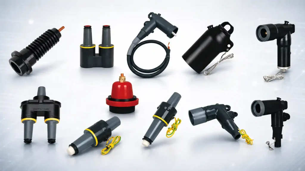
A Separable Connector is a cable accessory designed to connect a power cable to a compatible equipment bushing through a defined plug-in or mechanically secured interface.
It is commonly used in medium-voltage distribution systems where transformers, switchgear, ring main units, compact substations, and cable distribution equipment are equipped with standardized bushing interfaces.
Depending on the system, separable connectors may include:
- Loadbreak elbow connectors
- Deadbreak elbow connectors
- Screened T-connectors
- Straight connectors
- Front and rear connectors
- Plug-in connector systems
The connector body does much more than hold the cable in place. A complete Separable Connector must carry current, provide insulation, control the electric field around the prepared cable end, maintain contact with the equipment interface, and provide the required screening or grounding structure.
One important characteristic is that the cable-to-equipment connection can be separated without completely rebuilding the cable termination every time the equipment is replaced or the connection arrangement changes.
However, separable does not automatically mean loadbreak.
Some connector systems are specifically designed for loadbreak operation under defined conditions, while deadbreak connectors must be disconnected only after the circuit has been de-energized. The operating method must therefore be confirmed from the connector system and equipment interface rather than assumed from the word “separable.”
What Is a Cable Termination?
A Cable Termination is installed at the end of a power cable to safely transition the cable’s internal conductor, insulation, semiconductor screen, metallic screen, and outer sheath into a connection suitable for electrical equipment.
In medium-voltage systems, common termination technologies include:
- Cold shrink terminations
- Heat shrink terminations
- Pre-molded terminations
- Indoor terminations
- Outdoor terminations
A conventional Cable Termination usually ends with a cable lug or terminal connector that is then bolted or otherwise connected to the equipment terminal or busbar.
The termination has to manage the electrical stress created where the cable’s semiconductor screen ends. It must also restore insulation and provide suitable creepage and environmental protection for the installation.
Unlike a screened Separable Connector connected directly to a compatible bushing, a conventional termination may leave the final terminal connection in an air-insulated space. The equipment therefore needs sufficient clearance around the energized parts.
This is one of the major practical differences between the two systems.
Is a Separable Connector Also a Type of Cable Termination?
In a broad engineering sense, there is some overlap.
A Separable Connector is installed at the end of a cable and performs many of the same basic functions as a termination. Some plug-in connector products are even described as plug-in terminations.
For project selection, however, it is useful to distinguish between:
Separable cable connection
and
Conventional fixed Cable Termination
The first normally connects the prepared cable directly to a compatible bushing through an insulated separable interface.
The second normally prepares the cable end for connection through a terminal lug, stud, busbar, or other fixed equipment terminal.
This distinction is more accurate than saying that one “terminates” a cable while the other does not.
Both must safely manage the end of the cable. The difference lies mainly in how the cable interfaces with the equipment after it has been prepared.
What Are the Main Differences Between a Separable Connector and Cable Termination?
The differences become clearer when the complete connection is considered rather than only the appearance of the accessory.
| Item | Separable Connector | Conventional Cable Termination |
| Main connection | Cable to compatible equipment bushing | Cable to terminal, stud, busbar, or other connection point |
| Connection structure | Plug-in or mechanically secured separable interface | Usually fixed after installation |
| Screening | Fully screened designs are common | Depends on termination and equipment arrangement |
| Exposed energized connection | Usually enclosed within the connector system | May require air clearance around the terminal connection |
| Equipment space | Well suited to compact equipment | Often requires suitable termination and clearance space |
| Disconnection | Designed to be separated according to its operating procedure | Usually requires removal of the terminal connection |
| Equipment interface | Bushing compatibility is critical | Terminal and lug arrangement is critical |
| Typical applications | Transformers, RMUs, switchgear, compact substations, cable branch equipment | Switchgear, transformers, motors, overhead transitions and other fixed terminal points |
| Maintenance | Can simplify equipment disconnection and replacement | Often requires more work at the terminal connection |
| Selection focus | Cable + connector + bushing interface | Cable + termination kit + terminal arrangement |
Neither structure is automatically better.
The correct choice depends on how the equipment is designed and how the cable connection is expected to operate throughout its service life.
Why Is the Equipment Interface So Important?
The equipment interface is usually the first major difference to check.
A Separable Connector cannot simply be installed on any transformer or switchgear terminal because the mating bushing must be compatible with the connector.
The project may involve different interface systems depending on voltage class, current rating, regional standard, and equipment design.
For example, a 200A loadbreak elbow system uses a different connection structure from a higher-current screened T-connector system. Even when two accessories have similar voltage ratings, that does not mean that their mechanical and electrical interfaces are interchangeable.
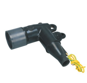
Before selecting a Separable Connector, it is necessary to confirm details such as:
- System voltage
- Rated current
- Bushing interface
- Cable conductor size
- Cable insulation diameter
- Conductor material
- Loadbreak or deadbreak requirement
- Available installation space
A conventional Cable Termination follows a different interface logic.
The termination kit must still match the cable voltage, conductor size, insulation diameter, screen structure, and installation environment, but the final connection is generally made through a lug or terminal connector.
The equipment-side question becomes:
What terminal or busbar will the cable lug connect to?
For a Separable Connector, the question is more often:
What bushing interface is installed on the equipment?
This difference can determine the entire accessory configuration.
How Does Installation Space Affect the Choice?
Installation space is especially important in modern compact medium-voltage equipment.
Ring main units, compact switchgear, pad-mounted transformers, compact substations, and cable branch equipment may have limited room around the cable connection area.
A screened Separable Connector can provide a compact connection because the insulation, electric field control, contact system, and outer screen are integrated into the connector assembly.
The cable can enter the equipment and connect directly to the designated bushing without requiring a large air-insulated termination chamber.
This can be useful where:
- Cable boxes are compact
- Phase spacing is limited
- Several cables must be arranged in one compartment
- Equipment dimensions need to remain small
- Fully insulated connection points are preferred
A conventional Cable Termination may require more clearance between phases and between energized components and grounded metalwork, depending on the voltage, termination design, and equipment configuration.
This does not mean conventional terminations always require a large installation area. Many compact termination systems are available.
The important point is that the required space is determined differently.
For a Separable Connector, connector body dimensions, cable bending radius, bushing spacing, and front clearance are important.
For a Cable Termination, terminal height, phase clearance, cable bending radius, creepage distance, and busbar location may become more important.
What Is the Difference in Insulation and Screening?
Both systems must control electrical stress around the cable end, but they may do so through different structures.
A screened Separable Connector typically combines several functional layers in one molded body.
Depending on the connector design, these can include:
- Internal conductive layer
- Main insulation layer
- Stress-control structure
- Outer conductive screen
- Cable conductor contact
- Grounding connection
The outer conductive screen can normally be connected to earth, helping maintain a defined electrical field around the connector.
The energized cable connection is therefore enclosed within the connector body rather than left exposed in the equipment compartment.
A conventional medium-voltage Cable Termination also controls electric stress at the end of the cable screen. Cold shrink, heat shrink, and pre-molded designs use different stress-control methods to manage the transition.
The final conductor lug, however, may remain part of an air-insulated terminal connection.
For indoor switchgear with sufficient clearance, this may be completely appropriate.
For compact equipment designed around screened bushings, a Separable Connector may fit the equipment architecture more naturally.
Does a Separable Connector Make Maintenance Easier?
It can, particularly when equipment replacement or cable reconfiguration is expected.
Suppose a cable is connected to a transformer through a compatible Separable Connector. If the transformer needs to be isolated and replaced, the connector can be disconnected according to the approved procedure and then connected to compatible replacement equipment.
The cable does not necessarily need a completely new termination each time.
A similar advantage can apply to:
- Ring main unit replacement
- Switchgear maintenance
- Cable testing
- Network reconfiguration
- Temporary grounding
- Addition of compatible accessories
- Equipment expansion
With a conventional Cable Termination, the cable lug may need to be unbolted from the terminal or busbar. Depending on the condition of the termination and the equipment arrangement, additional cable work may also be required.
The difference should not be exaggerated, however.
A Separable Connector still requires correct isolation procedures, inspection, cleaning, and installation practices. Deadbreak connectors cannot be treated as energized plug-and-play components simply because they are removable.
Maintenance convenience is one advantage of the structure, not a replacement for safe operating procedures.
Can Every Separable Connector Be Disconnected Under Load?
No.
This is one of the most important distinctions in medium-voltage cable accessory selection.
A loadbreak Separable Connector is specifically designed for connection and disconnection under defined energized operating conditions when used with the correct mating components, tools, and procedures.
A deadbreak Separable Connector must normally be operated only after the circuit has been de-energized.
The difference is part of the connector design and complete interface system.
Therefore:
Separable ≠ automatically loadbreak.
A project that requires load switching must confirm this requirement before connector selection.
For many higher-current main circuit applications, the primary requirement may be a stable screened connection rather than routine loadbreak operation. In these cases, a deadbreak connector can be entirely appropriate.
Where Is a Separable Connector Commonly Used?
A Separable Connector is particularly suitable for equipment already designed with compatible medium-voltage bushings.
Common applications include:
Pad-Mounted Transformers
Underground distribution cables can connect to transformer bushings through loadbreak or deadbreak connector systems depending on the current rating and network design.
This arrangement creates a compact cable interface and supports the modular connection structures commonly used in underground distribution systems.
Ring Main Units
RMUs often have compact cable compartments and defined bushing interfaces.
Screened separable connectors can fit directly onto these bushings while keeping the cable connection enclosed and organized.
Medium-Voltage Switchgear
When the switchgear is designed for plug-in or screened cable interfaces, a Separable Connector can provide a compact connection between incoming or outgoing cables and the equipment.
Compact Substations
Space inside a compact substation is limited, and transformers and switchgear may be installed close together.
A separable connection system can help reduce the space required around cable interfaces while supporting future equipment maintenance.
Cable Branch Boxes and Distribution Equipment
Separable connector systems can also be combined with compatible junctions, bushings, protective caps, grounding accessories, and surge protection components to create different cable distribution layouts.
Where Is a Conventional Cable Termination More Suitable?
Conventional Cable Terminations remain widely used because many electrical systems are built around open terminal or busbar connections.
They can be suitable for:
- Air-insulated switchgear
- Transformer terminal arrangements
- Motors
- Indoor electrical rooms
- Outdoor cable-to-equipment connections
- Cable-to-overhead-line transitions
- Industrial equipment with fixed terminal connections
Outdoor terminations are particularly important where a cable transitions into an exposed connection and sufficient creepage and weather resistance are required.
The decision should follow the equipment design.
If the equipment provides a conventional terminal pad or busbar rather than a compatible bushing, installing a Separable Connector simply for the sake of using a separable system would normally make little sense.
Likewise, if the equipment is specifically designed around screened bushings, converting the connection to a conventional exposed termination may add unnecessary complexity.
Which One Is Better for Transformers?
There is no single answer because transformers can use different connection structures.
A pad-mounted transformer in an underground distribution network may be designed around 200A or higher-current separable interfaces. In that case, a Separable Connector is a natural part of the transformer connection system.
Another transformer may have conventional terminals inside a cable box or enclosure. A heat shrink, cold shrink, or other Cable Termination may be the more appropriate connection.
The transformer specification should therefore be checked for:
- Bushing or terminal type
- Voltage class
- Continuous current
- Cable size
- Number of cable connections
- Required switching method
- Available cable compartment space
The accessory should follow the transformer interface rather than forcing the transformer connection to follow a preferred accessory.
Which One Is Better for Switchgear?
The same principle applies to switchgear.
Some medium-voltage switchgear uses air-insulated cable terminals and is designed for conventional Cable Terminations.
Other compact or gas-insulated equipment uses standardized bushings designed for screened Separable Connectors.
The correct selection therefore begins with the equipment drawing.
For separable systems, bushing interface compatibility must be confirmed.
For conventional terminations, the terminal dimensions, lug hole pattern, phase clearance, cable routing, and termination space must be checked.
This is why simply asking for “a 15kV cable accessory” or “a 24kV termination” does not provide enough information to select the complete connection.
What Cable Information Is Needed for Both Systems?
Although their equipment interfaces differ, a Separable Connector and a conventional Cable Termination still share several important cable selection requirements.
Before ordering either type, confirm:
System Voltage
The accessory must match the electrical requirements of the cable network.
Cable Conductor Size
The conductor connector or lug must fit the actual conductor cross-section.
Copper or Aluminum Conductor
Conductor material affects the contact or terminal selection and installation method.
Cable Insulation Diameter
This is especially important for molded and pre-molded accessories.
Nominal conductor size alone does not always provide the actual insulation diameter needed for accessory selection.
Cable Construction
Single-core or three-core construction, shielding system, armor, outer sheath, and semiconductor structure can affect the termination kit.
Installation Environment
Indoor, outdoor, underground, humid, polluted, or confined installations may require different accessory designs and protection methods.
These details should be confirmed before choosing a product model.
Can Separable Connectors and Cable Terminations Be Used in the Same Project?
Yes.
A power distribution project does not need to choose one technology for every cable end.
One end of a medium-voltage cable may use a Separable Connector because it enters compact switchgear through a screened bushing.
The other end of the same cable may use a conventional outdoor Cable Termination because it connects to different equipment with an exposed terminal structure.
The selection depends on the interface at each end.
For example:
Cable End A: Screened Separable Connector → RMU bushing
Cable End B: Outdoor Cable Termination → exposed equipment terminal
There is no conflict in using both.
The objective is to make each cable end compatible with the equipment it connects to while maintaining the required insulation, electrical stress control, current capacity, and environmental protection.
How Should You Decide Between a Separable Connector and Cable Termination?
Start with the equipment rather than the accessory catalog.
Ask the following questions:
- Does the equipment have a standardized medium-voltage bushing or a conventional terminal?
- Is a screened and enclosed connection required?
- Will the equipment need to be disconnected or replaced during future maintenance?
- Does the system require loadbreak capability, or will all disconnection occur after isolation?
- How much cable termination space is available?
- What are the cable conductor size and actual insulation diameter?
- What voltage and continuous current must the connection carry?
- Will the connection be indoors, outdoors, underground, or exposed to moisture or contamination?
If the equipment is designed around a compatible bushing and a compact screened connection is required, a Separable Connector is often the logical choice.
If the cable connects to a conventional terminal or busbar and a fixed connection fits the equipment design, a Cable Termination may be more appropriate.
A Separable Connector Is Not Simply a More Advanced Cable Termination
It can be tempting to think of a Separable Connector as an upgraded version of a conventional Cable Termination.
That is not the best way to compare them.
They are different connection approaches designed around different equipment interfaces.
A conventional termination can be exactly the right solution for an air-insulated terminal arrangement.
A screened Separable Connector can be exactly the right solution for a compact transformer or switchgear bushing.
The more useful question is not:
Which technology is better?
It is:
Which connection structure matches the cable, equipment interface, operating method, and maintenance requirements of the project?
Once these conditions are clear, product selection becomes much more straightforward.
FAQ
Is a Separable Connector the same as a Cable Termination?
Not exactly. Both are used at cable ends, but a Separable Connector normally connects the cable to a compatible equipment bushing through a removable insulated interface, while a conventional Cable Termination usually connects the cable to a fixed terminal or busbar.
Can a Separable Connector be used on any transformer?
No. The transformer must have a compatible bushing interface. Voltage class, current rating, interface type, cable dimensions, and connector design must all match.
Can all Separable Connectors be disconnected while energized?
No. Only connector systems specifically designed and rated for loadbreak operation may be operated under the defined energized conditions. Deadbreak connectors require the circuit to be de-energized before separation.
Is a Separable Connector suitable for switchgear?
Yes, when the switchgear is equipped with the appropriate bushing interface. Screened separable connectors are commonly used with compact medium-voltage switchgear and RMUs.
Can Cable Terminations and Separable Connectors be used in the same cable system?
Yes. Different cable ends can use different termination structures according to the equipment interface at each end.
Conclusion
A Separable Connector and a conventional Cable Termination both create a safe transition between a medium-voltage cable and electrical equipment, but they do not create that connection in the same way.
A Separable Connector normally uses a compatible bushing to create an insulated, removable, and often fully screened cable-to-equipment interface. A conventional Cable Termination prepares the cable for a more fixed connection to a terminal, lug, stud, or busbar.
The right choice depends on the equipment interface, cable dimensions, voltage and current requirements, installation space, operating method, and future maintenance plan.
For transformers, switchgear, RMUs, compact substations, and other medium-voltage equipment, confirming these details before ordering helps avoid mismatched bushings, unsuitable cable ranges, insufficient installation space, and incorrect operating structures.
YIEOU supplies Separable Connector systems and related medium-voltage cable accessories for different distribution configurations. When project cable data and equipment interface information are available, the connector, bushing, contact components, and related accessories can be coordinated as one complete connection system rather than selected as isolated parts.