
Underground distribution networks reduce exposure to wind, falling branches, traffic and other external hazards associated with overhead lines. However, placing cables below ground does not remove every reliability risk. Cable joints, transformer connections, branch points and switchgear interfaces can still become weak points, while faults are often more difficult to locate and repair than they are on an overhead feeder.
一个正确选择的 可分离连接器 helps address these challenges by creating an insulated, shielded and removable connection between a medium-voltage cable and compatible equipment. It can be installed on pad-mounted transformers, cable branch boxes, sectionalizing cabinets, switchgear and other underground distribution equipment.
The reliability benefit does not come from the connector body alone. It comes from matching the cable, conductor, equipment bushing, connector interface, grounding arrangement and supporting accessories as one complete system.
Why Are Cable Connection Points Critical in Underground Distribution?
An underground cable may run for hundreds of metres without an exposed conductor, yet every termination or branch point creates a change in the electrical and mechanical structure.
At a typical equipment connection, the cable conductor must be joined to a terminal, the insulation screen must be correctly controlled, the electric field must be managed, the external shield must remain grounded, and the connection must be protected against moisture and contamination.
A problem in any of these areas may lead to:
- Increased contact resistance
- Local temperature rise
- 局部放电
- Insulation deterioration
- 表面追踪
- Moisture entry
- Flashover
- Unplanned feeder outages
A Separable Connector combines several of these functions within a moulded connection system. IEEE 386 establishes ratings, service conditions, construction features and tests for shielded loadbreak and deadbreak separable insulated connector systems used on medium-voltage distribution networks. The current IEEE 386-2025 edition covers applicable systems from 15 kV through 35 kV.
This standardized connection approach is especially valuable in underground distribution because the interface can be inspected, isolated or reconfigured without replacing an entire cable length.
How Does a Shielded Connector Protect the Cable Interface?
A properly assembled Separable Connector provides more than basic conductor insulation. Its moulded structure is designed to continue the cable’s electrical shielding and stress-control functions through the connection point.
Insulation around the energized connection
The insulating body surrounds the conductor terminal, probe or contact area, helping prevent accidental contact and electrical discharge to nearby grounded equipment.
External semiconductive shielding
The outer conductive or semiconductive layer maintains a grounded external surface when correctly connected to the grounding system. This helps control the electric field around the connector and allows compact installation inside pad-mounted equipment and cable cabinets.
Controlled cable-screen transition
The cable screen cannot simply end at an arbitrary point. The connector structure and cable preparation dimensions must work together to control electrical stress where the cable screen is removed.
环境密封
Underground vaults and pad-mounted equipment may be exposed to condensation, standing water, dust and seasonal temperature changes. Fully shielded, insulated and submersible connector designs are widely used for connections between underground cables and transformers, switchgear or sectionalizing equipment.
These features can reduce the exposure of energized interfaces, but they do not compensate for incorrect installation. Cable preparation, cleanliness, lubrication, connector seating and grounding must still follow the specified procedure.
How Do Separable Connectors Support Fault Isolation?
A permanent cable joint may provide a reliable connection, but it offers limited flexibility when a feeder section must be isolated. A Separable Connector allows the cable to connect through a defined removable interface.
In a loop-fed underground system, this can help operators separate a damaged cable section from the healthy parts of the network. Depending on the network design, unaffected sections may then be returned to service through another feed direction or switching point.
For example, 200A loadbreak elbows and compatible junctions can be used in underground distribution arrangements that require cable loops, taps, splices or sectionalizing points. The connector should only be operated within its loadbreak rating and under the approved operating procedure.
The benefit is not that every underground fault becomes easy to repair. The benefit is that the network can include planned connection and isolation points instead of depending entirely on permanent cable joints.
This can improve:
- Faulted-section isolation
- Feeder reconfiguration
- Transformer replacement
- Cable testing preparation
- Maintenance access
- Restoration of healthy circuits
Where several feeders enter a cable branch box, correctly arranged junctions, busbars and connectors can also make the circuit layout easier to identify. Clear circuit identification reduces the risk of disconnecting or grounding the wrong cable during maintenance.
Why Does Interface Matching Affect Long-Term Reliability?
Two components marked with the same voltage and current ratings are not automatically compatible. The actual mating interface, cable dimensions and conductor connection must also correspond.
A Separable Connector may appear to fit during installation but still create reliability problems if the interface geometry is incorrect. Possible consequences include incomplete seating, insufficient contact pressure, damage to the bushing surface or abnormal electric-field concentration.
The project should therefore confirm:
- 系统电压
- Continuous current requirement
- Cable conductor size
- 铜或铝导体
- Cable insulation material
- 电缆绝缘层外径
- 电缆屏蔽层结构
- Connector interface type
- 设备套管图
- 可用橱柜空间
- 电缆入口方向
- Required operating category
The equipment bushing and the connector must be reviewed as one interface. YIEOU’s product range includes cable-side connectors and related equipment-side parts, such as bushing inserts, integral deadbreak bushings, junctions, busbars and protective caps. This allows the connection arrangement to be checked before production rather than leaving interface matching until installation.
Correct matching also affects temperature rise. At normal load, a stable conductor connection should maintain the required contact pressure and a low-resistance current path. Incorrect terminals, poor crimping, loose threaded components or incomplete connector engagement may produce localized heating that accelerates insulation aging.
Should an Underground Network Use 200A or 600A Connectors?
The current class should reflect the actual circuit role rather than a general preference for a larger connector.
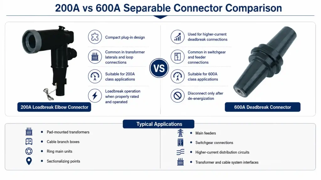
啊 200A loadbreak Separable Connector is commonly used on pad-mounted transformers, loadbreak junctions and sectionalizing equipment. It provides a compact plug-in connection and, where the complete system is appropriately rated, can support specified load-make and loadbreak operations.
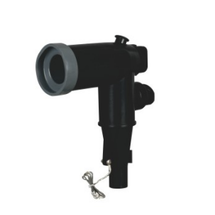
啊 600A deadbreak Separable Connector is more suitable for higher-current feeders and equipment connections. It is commonly configured as a T-shaped connector connected to a compatible 600A bushing or busbar. A deadbreak connector must not be separated under load. The circuit must first be de-energized, isolated, tested and grounded according to the applicable safety procedure.
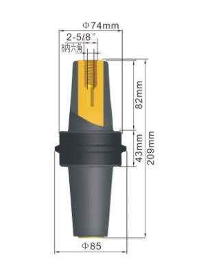
YIEOU manufactures 15kV and 25kV 200A loadbreak connector systems, together with 15kV and 24kV 600A deadbreak connector components. The supporting range includes bushings, junctions, busbars, insulated caps, grounding elbows and elbow surge arresters.
| 比较点 | 200A 负载断开系统 | 600A 绝缘穿刺连接器 |
| Typical network role | Transformer laterals, loops and sectionalizing points | Main feeders and higher-current equipment connections |
| Common connector form | 弯头连接器 | T型连接器 |
| 设备接口 | 负载断开套管插入件或接头 | 集成式或设备安装式绝缘穿刺接头 |
| Operating condition | Specified loadbreak operation within the approved rating and procedure | Disconnection only after de-energization and isolation |
| Common accessories | Junctions, grounding elbows, caps and elbow arresters | Busbars, connector plugs, bushings, extensions and caps |
| Main selection focus | Cable size, interface, switching duty and operating method | Cable size, interface, current, contact assembly and equipment space |
Selecting 600A equipment for a 200A circuit does not automatically make the system more reliable. Larger components may require more cabinet space, a different cable arrangement and a different operating procedure. Reliability comes from selecting the appropriate interface for the feeder design.
How Do Junctions Improve Network Flexibility?
Underground networks often require more than one cable-to-equipment connection. They may need a loop point, branch point, temporary test location, spare way or sectionalizing position.
A loadbreak junction provides multiple compatible interfaces in one grounded assembly. Depending on its configuration, it can support:
- Incoming and outgoing cable loops
- Branch connections
- Cable splicing
- Sectionalizing points
- 临时接地
- Connection of test or maintenance equipment
- Future feeder expansion
This modular structure can reduce the number of permanent joints required inside a vault or cabinet. It also gives system planners a defined point for future changes.
For higher-current networks, 600A busbars and T-connector arrangements can perform a similar system-organizing role. Standard, shaped and mixed-current busbars may be used where several cable directions or both 200A and 600A interfaces must be incorporated into the same distribution arrangement.
The busbar layout should be confirmed during equipment design. Adding a separable connector after the switchgear or branch cabinet has already been manufactured may create insufficient bending space, poor cable alignment or excessive mechanical stress on the bushing.
How Do Grounding and Protective Accessories Reduce Maintenance Risk?
Reliability includes the ability to perform maintenance without damaging the cable system or leaving interfaces improperly protected.
肘部触地
A grounding elbow can be installed on a compatible de-energized interface as part of the approved grounding procedure. It provides a visible connection between the cable circuit and ground, helping maintenance personnel establish and verify the required grounded condition.
A grounding elbow does not replace isolation, voltage testing or the site’s lockout procedure. It is one part of a complete safe-working arrangement.
绝缘保护帽
An unused bushing or junction interface should not be left exposed. A compatible insulated cap protects the interface against moisture, dust, accidental contact and mechanical damage.
Protective caps are important for spare ways intended for future expansion. Without suitable protection, a spare bushing may deteriorate before it is ever placed in service.
Capacitive test points
Some elbow connector configurations include a capacitive test point. This can assist with circuit-status checking when used with suitable equipment and procedures. It should not be treated as a substitute for the approved voltage-detection and safety process.
弯头浪涌抑制器
An elbow surge arrester can be connected to a compatible interface to help limit incoming overvoltage from lightning or switching events. It is particularly useful where surge protection is required close to a transformer, switchgear cabinet or underground cable entry point.
Together, these accessories turn the Separable 连接器 into part of a broader maintenance and protection system rather than an isolated cable termination.
What Reliability Risks Should Be Checked During Selection?
The following table connects common underground distribution risks with the relevant connector decisions.
| Underground distribution risk | 连接器系统如何提供帮助 | 确认信息 |
| Moisture or contamination at the interface | Insulated, shielded and sealed connection structure | Installation environment and sealing arrangement |
| Local heating | Stable conductor terminal and matched contact interface | Conductor size, terminal type and assembly method |
| 局部放电 | Controlled insulation geometry and cable-screen transition | Cable insulation diameter and preparation dimensions |
| Difficult fault isolation | Removable connectors and planned sectionalizing points | Network diagram and operating sequence |
| 外露备用衬套 | 绝缘保护帽 | Interface and voltage class |
| Unsafe maintenance grounding | Compatible grounding elbow and defined grounding point | Grounding procedure and accessory rating |
| Surge entering underground equipment | Elbow surge arrester near the connection point | 系统电压与保护配合 |
| Wrong connector installed on site | Clear model matching, labels and complete kits | Cable data, bushing drawing and accessory list |
| Excessive cable bending force | Suitable connector orientation and cabinet clearance | Cable entry direction and minimum bending radius |
| Incomplete future expansion plan | Junction, busbar or spare-interface arrangement | Number of present and future circuits |
This review should take place before the purchase order is finalized. Waiting until cable installation begins can lead to missing accessories, unsuitable terminals or insufficient equipment clearance.
What Should Be Included in a Separable Connector Enquiry?
A clear enquiry allows the separable connector manufacturer to evaluate the entire connection rather than recommend a connector from voltage and conductor size alone.
For an underground distribution project, provide:
- Single-line diagram or connection diagram
- System nominal and maximum voltage
- 所需连续电流
- 负载断开或失电断开要求
- Cable manufacturer and cable type
- Conductor material and cross-sectional area
- Diameter over conductor screen
- 电缆绝缘层外径
- Insulation and jacket material
- Equipment type and model
- Bushing interface drawing
- 电缆入口方向
- Available installation space
- Required junction, cap, grounding or surge accessories
- Applicable standard and test requirements
- Quantity, packaging and marking requirements
Photographs can help identify an existing installation, but photographs alone are normally insufficient for final matching. Dimensions, equipment drawings and cable data should be provided wherever possible.
How Does Manufacturing Control Support Connection Reliability?
A reliable design still depends on consistent production. The moulded insulation, semiconductive layers, conductor components and equipment interface must remain within the specified material and dimensional requirements.
Important manufacturing controls include:
- Rubber material identification and storage
- Prevention of dust and metal contamination
- Stable moulding and curing conditions
- Control of insulating and semiconductive layer positions
- Interface dimensional inspection
- Terminal and probe identification
- 表面检测
- Assembly verification
- Electrical testing
- Complete-kit and label inspection
YIEOU manufactures both rubber-moulded connector components and related epoxy equipment-side interfaces. Its production and inspection capabilities include automatic rubber injection, epoxy moulding, material analysis, voltage-withstand testing and partial-discharge testing.
For project buyers, the practical advantage is coordinated control of the connector, bushing and supporting accessories. When these parts are reviewed together, it becomes easier to confirm interface compatibility, package the correct installation kit and maintain consistency across repeat orders.
常见问题解答
Can a Separable Connector prevent every underground cable fault?
No. It cannot prevent damage elsewhere in the cable, incorrect installation, external excavation damage or system overloading. It improves the reliability of the cable-to-equipment interface when the product is correctly selected, installed and operated.
Can a 200A loadbreak elbow be disconnected while energized?
Only when the complete connector system is specifically rated for loadbreak operation and the work is performed using the approved tools, procedures and operating conditions. Product ratings and local safety requirements must be followed.
Can a 600A deadbreak connector be used for routine switching?
No. A deadbreak connector is not a load-switching device. It must only be separated after the circuit has been properly de-energized, isolated, tested and grounded.
Why is the cable insulation diameter required?
The conductor size identifies the electrical conductor, but it does not define the outside dimensions of the cable insulation. The connector or cable adapter must match the actual insulation diameter to achieve the intended fit, stress control and sealing.
Should protective caps be ordered for unused interfaces?
Yes. Every unused compatible bushing, junction or busbar interface should receive the specified insulated protective cap. Leaving the interface exposed can allow moisture, dirt or physical damage to affect future operation.
Build Underground Reliability Around the Complete Connection
Separable Connectors improve underground distribution reliability by protecting cable interfaces, supporting controlled electric fields, maintaining grounded shielding and providing removable connection points for isolation, testing and network reconfiguration.
Their greatest value appears when the complete system is planned together. The cable, conductor terminal, connector body, bushing, junction, grounding accessory, protective cap and surge-protection arrangement must all correspond.
YIEOU supplies 200A loadbreak and 600A deadbreak Separable Connector systems for medium-voltage underground distribution applications. Our range includes elbow connectors, T-shaped connectors, bushing inserts, integral bushings, junctions, busbars, grounding elbows, insulated caps and elbow surge arresters.
YIEOU provides 200A loadbreak and 600A deadbreak Separable Connector systems for underground distribution projects, together with matching bushings, junctions, busbars, grounding elbows, protective caps and surge arresters. By reviewing the cable specifications, equipment interface and network layout together, we can help confirm a connection arrangement suited to the actual installation. For product selection or interface matching, please send us the cable datasheet, system voltage, current rating and bushing drawing, and contact YIEOU for further support.