
A Separable Connector is a compact medium-voltage cable accessory, but its internal structure performs several functions at the same time. It must carry current, maintain insulation, control electrical stress, continue the shielding system, fit the equipment interface, and protect the connection from environmental exposure.
Because these functions are concentrated within one molded and assembled component, a small manufacturing deviation can affect more than appearance. Incorrect material distribution, dimensional variation, surface contamination, conductor misalignment, or incomplete assembly may influence installation fit, electrical contact, insulation performance, or long-term stability.
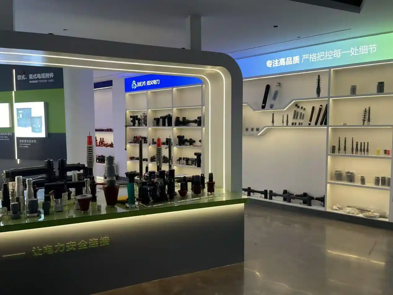
At YIEOU, Separable Connector quality control is organized around the defects that can occur during material preparation, rubber injection, epoxy molding, curing, component assembly, electrical testing, identification, and packaging. The purpose is not simply to produce a connector that looks complete. It is to produce a repeatable cable-to-equipment interface that matches the confirmed product structure.
Quick Answer: Which Separable Connector Defects Require the Most Attention?
The most important manufacturing defects are those that affect the insulation system, electric-field distribution, current-carrying path, or mating interface.
Typical concerns include:
- Contamination in insulating materials
- Incomplete rubber filling
- Incorrect curing conditions
- Misaligned semiconductive layers
- Voids or irregular internal interfaces
- Dimensional deviation at mating surfaces
- Flash, scratches, or damage on functional interfaces
- Incorrect conductor terminals or contact components
- Mixed, missing, or incorrectly identified installation parts
Some defects can be detected by visual or dimensional inspection. Others require process records, electrical testing, or partial-discharge evaluation because they may not be visible from the outside.
Table 1: Common Separable Connector Manufacturing Defects
| Manufacturing defect | Possible production cause | Potential project impact | Main factory control |
| Material contamination | Poor storage, handling or equipment cleaning | Reduced insulation consistency or surface defects | Material identification, controlled storage and equipment cleaning |
| Incomplete rubber filling | Unstable injection condition or blocked mold flow | Missing material, irregular geometry or weak areas | Injection parameter control and molded-part inspection |
| Incorrect curing | Unsuitable curing temperature or time | Unstable mechanical or electrical properties | Defined curing process and batch records |
| Semiconductive layer misalignment | Insert movement or molding deviation | Uneven electrical stress or incomplete shielding structure | Mold positioning and section or process inspection |
| Internal void or irregular interface | Air entrapment, contamination or poor material flow | Localized electrical activity or reduced insulation reliability | Process control and applicable partial-discharge evaluation |
| Dimensional deviation | Mold wear, process variation or incorrect setup | Difficult installation or incomplete mating | Mold maintenance and dimensional inspection |
| Interface flash or scratches | Poor trimming, handling or demolding | Surface damage, improper seating or installation difficulty | Surface inspection and protected handling |
| Incorrect terminal or probe | Component mixing or incomplete specification confirmation | Poor fit, unstable connection or assembly failure | Component identification and assembly verification |
| Missing or mixed kit parts | Packaging or model-control error | Installation delay or incorrect field assembly | Package checklist, model labeling and final inspection |
Material Contamination Can Create Hidden Insulation Weaknesses
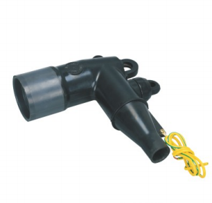
A Separable Connector normally contains insulating rubber, semiconductive material, conductive components, metal fasteners, and other molded or assembled parts. Each material has a defined role, and contamination between these materials can affect the finished structure.
Dust, metal particles, oil, moisture, fibers, cleaning residues, or material left from a previous production batch may enter the molding process when storage and equipment-cleaning procedures are not properly controlled.
Why Contamination Is More Serious Than a Cosmetic Mark
A surface mark may be visible and easy to reject. Internal contamination is more difficult because it may become enclosed within the insulating or semiconductive structure during injection and curing.
Depending on its position and severity, contamination may contribute to:
- Irregular material flow
- Weak bonding between molded layers
- Local surface defects
- Unstable insulation characteristics
- Concentrated electrical stress
- Abnormal partial-discharge behavior
This does not mean that every small visual mark represents an electrical failure. The location, depth, material type, and effect on the functional interface must be evaluated.
How the Factory Controls Material Cleanliness
Material control begins before injection molding. The insulating and semiconductive compounds should be clearly identified, stored separately, protected from contamination, and used according to the confirmed production process.
Mixing, processing, injection, curing, trimming, and inspection areas should also prevent unnecessary contact with dust, metal chips, oils, or unrelated materials.
At YIEOU, automatic rubber injection and material-processing equipment are combined with incoming-material checks and process inspection. Our factory also uses material-analysis equipment to support verification where the product or production requirement calls for additional evaluation.
Incomplete Rubber Filling Can Distort the Separable Connector Structure
During rubber injection, the material must reach the required areas of the mold and reproduce the designed geometry. If material flow is insufficient or unstable, the finished connector body may contain incomplete sections, irregular edges, thin areas, or poorly formed internal features.
This problem may be associated with:
- Incorrect material quantity
- Unstable injection pressure
- Unsuitable mold temperature
- Restricted flow channels
- Material-processing variation
- Incorrect component positioning
- Air trapped during filling
- Insufficient mold maintenance
Functional Areas Require More Attention Than General Appearance
The most important concern is not whether the external shape looks perfectly decorative. Greater attention should be given to functional areas such as:
- The cable-entry channel
- Equipment mating interface
- Stress-control region
- Semiconductive shield structure
- Probe or contact opening
- Test-point structure
- Grounding connection
- Sealing and seating surfaces
An incomplete non-functional edge may be handled differently from missing material within an insulating or mating surface. Inspection criteria should therefore distinguish critical functional zones from ordinary external surfaces.
Injection Parameters Must Be Repeatable
Stable injection production requires defined equipment settings and controlled material preparation. Changes in compound condition, mold temperature, injection sequence, or curing cycle can influence how the mold fills.
YIEOU uses automatic rubber injection machinery and industrial production equipment to support repeatable connector-body molding. Process inspection is performed before the product reaches final assembly so that obvious molding defects are not carried into later production stages.
Incorrect Curing Can Affect Both Strength and Elasticity
After injection, the rubber component must be cured under suitable conditions. Curing helps establish the final physical and functional properties of the molded material.
A curing process that is too short, too long, too cool, or too hot may influence:
- Elastic recovery
- Mechanical strength
- Surface condition
- Dimensional stability
- Material hardness
- Layer bonding
- Long-term aging behavior
The effect may not always be immediately visible after demolding.
Why Elastic Behavior Matters at the Interface
Many Separable Connector designs rely on the molded body maintaining suitable pressure around the cable adapter, equipment bushing, insulating plug, or related mating component.
If the material does not recover or compress as intended, the interface may become more difficult to install or may not maintain the designed mechanical relationship.
Curing control is therefore connected to both material quality and dimensional consistency.
Production Records Help Maintain Batch Stability
A defined curing process should record or control the necessary production conditions for the specific material and molded part.
Where the same connector is supplied in repeated batches, stable curing procedures help reduce changes in hardness, flexibility, appearance, and fit between one production run and another.
Misaligned Semiconductive Layers Can Affect Electric-Field Control
The semiconductive structure of a Separable Connector is not simply a black external coating. Internal and external semiconductive sections may perform different shielding and stress-control functions.
Their position must correspond with the conductor connection, cable insulation cutback, molded insulation body, grounding structure, and equipment interface.
Misalignment May Not Be Visible Externally
A connector can appear normal from the outside while an internal semiconductive section is:
- Shifted from its intended position
- Unevenly distributed
- Partially interrupted
- Too close to an unintended area
- Incompletely bonded to the adjacent material
- Distorted by component movement during molding
These conditions can change the designed electrical-field distribution.
Insert Positioning Must Remain Stable During Molding
Where molded layers or inserted components are used, the mold must hold them in the correct position during injection and curing.
Positioning fixtures, mold structure, component dimensions, and production handling all contribute to alignment.
Factory control therefore includes more than checking the finished exterior. It also involves confirming that the molding process can repeatedly reproduce the intended internal structure.
Internal Voids May Lead to Abnormal Partial-Discharge Activity
Voids can be formed by air entrapment, poor material flow, contamination, incomplete bonding, or irregular molding conditions. Their significance depends on their size, location, surrounding material, and electrical stress.
A void close to a highly stressed region is generally more important than a harmless external indentation located outside the functional insulation path.
Why Visual Inspection Alone Is Not Enough
A fully molded connector may hide an internal defect that cannot be identified through normal external inspection.
This is one reason electrical evaluation is used for medium-voltage cable accessories. Partial-discharge testing can provide information about localized electrical activity associated with defects or irregular insulation conditions.
Partial discharge is not the same as complete insulation breakdown. It is localized electrical activity that does not completely bridge the insulation between conductors. Repeated discharge activity in a stressed insulation region may contribute to deterioration over time.
IEEE 386 establishes ratings, construction features, service conditions, and tests for shielded loadbreak and deadbreak separable insulated connector systems within its applicable voltage and current range.
Testing Must Be Combined with Process Control
Electrical testing should not be treated as a method for correcting an unstable manufacturing process.
The preferred approach is to:
- Control material preparation.
- Maintain injection and curing conditions.
- Inspect molded components.
- Verify dimensions and assembly.
- Perform applicable electrical evaluations.
- Investigate abnormal results before release.
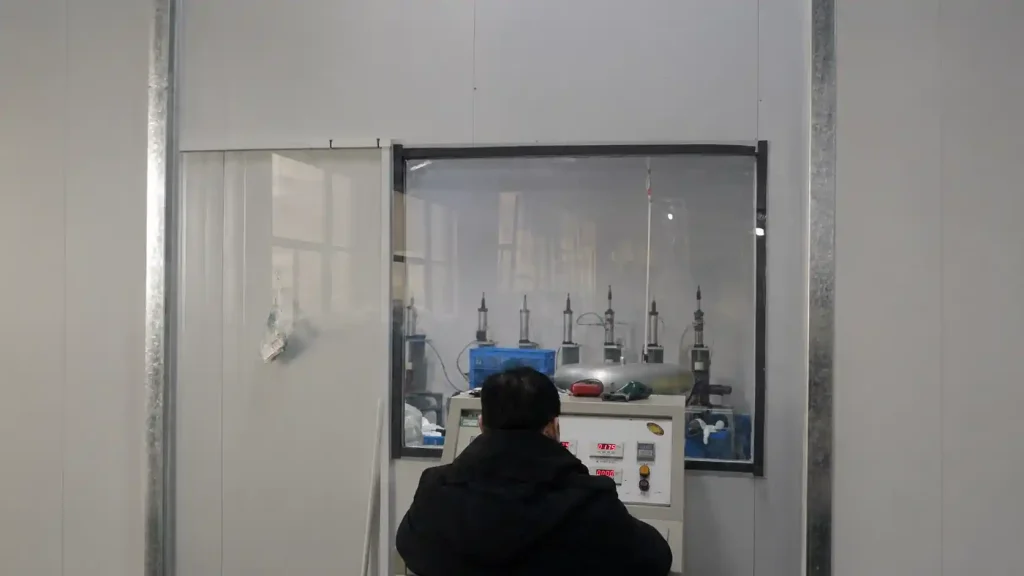
YIEOU has established dedicated partial-discharge and voltage-withstand testing facilities to support product verification. The applicable testing scope, sampling arrangement, acceptance criteria, and records depend on the product and confirmed order requirements.
Dimensional Deviation Can Prevent Correct Interface Mating
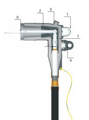
A Separable Connector must match both the cable and the equipment-side interface. Even when the connector has the correct general voltage and current class, dimensional deviation can make installation difficult or prevent full engagement.
Important dimensions may include:
- Internal cable or adapter diameter
- Interface cone geometry
- Depth of engagement
- Probe or contact position
- Terminal position
- Insulating plug interface
- External shield dimensions
- Bushing or insert mating surface
- Fastener and threaded component dimensions
A Separable Connector That Can Be Forced into Position Is Not Necessarily Correct
Excessive installation force may be a sign of dimensional mismatch, surface damage, contamination, an incorrect adapter, or an unsuitable mating component.
Forcing the connector into position may damage the molded body, equipment bushing, cable preparation, or internal connection components.
The objective of dimensional control is not to make every connector easy to install under every condition. It is to ensure that the product follows the confirmed design and matches the specified cable and equipment interface.
Mold Wear Must Be Monitored
Repeated production gradually affects molds, inserts, locating fixtures, and trimming tools. Wear may create:
- Changed interface dimensions
- Increased flash
- Uneven parting lines
- Poor component positioning
- Surface marks
- Reduced dimensional repeatability
Periodic mold inspection and maintenance help prevent gradual deviation from being accepted as normal production variation.
YIEOU combines automatic molding equipment with dimensional and molded-component inspection to maintain the functional geometry of Separable Connector bodies and related molded accessories.
Flash and Surface Damage Can Interfere with Installation
Mold flash is excess material formed around mold parting lines or openings. Some minor flash can be removed during normal finishing, but flash on a functional mating surface requires careful control.
Scratches, cuts, dents, tearing, and handling damage can also occur during demolding, trimming, assembly, testing, storage, or packaging.
Critical Surface Areas Need Separate Inspection
Not all external surfaces have the same importance. Inspection should pay particular attention to:
- Bushing mating surfaces
- Cable-entry regions
- Insulating plug interfaces
- Sealing surfaces
- Test-point areas
- Semiconductive shield edges
- Grounding interfaces
- Regions subjected to installation force
A shallow cosmetic mark away from the functional interface is different from a cut that enters the insulation or disrupts a sealing surface.
Reworking Must Not Create a New Defect
Removing flash with an unsuitable tool can create cuts, rough surfaces, or dimensional changes.
Rework should only be permitted where the product specification and inspection procedure allow it. Components with damage in critical insulation, shielding, sealing, or interface regions should not be released simply because the defect can be made less visible.
Incorrect Terminals and Contact Components Can Cause Connection Problems
The molded connector body may be correct while the internal conductive component is wrong.
Possible assembly errors include:
- Copper terminal supplied for an unconfirmed conductor configuration
- Incorrect terminal bore or conductor range
- Wrong probe or connecting screw
- Contact component from a different connector series
- Terminal inserted in the wrong orientation
- Missing washer, fastener, or contact part
- Component not seated to the specified position
These errors can affect assembly, current transfer, contact pressure, or cable preparation.
Similar Appearance Does Not Confirm Compatibility
Terminals, probes, adapters, plugs, and screws may look similar while having different dimensions or electrical functions.
Production and assembly personnel should identify components by controlled model information rather than appearance alone.
This becomes especially important when 200A loadbreak and 600A deadbreak products, several voltage classes, or multiple cable ranges are being produced in the same factory.
Assembly Inspection Should Confirm the Full Conductive Path
Inspection should verify that the conductor terminal, probe, connecting screw, contact component, and equipment-side interface belong to the same confirmed configuration.
The check should include both individual component identity and the completed assembly relationship.
Epoxy Component Defects Can Affect the Equipment-Side Interface
Separable Connector systems often include equipment-side components such as bushings, bushing wells, junctions, or other epoxy-insulated interfaces.
Epoxy molding introduces a different group of production concerns from flexible rubber components.
Potential defects may include:
- Embedded conductor movement
- Resin voids
- Incomplete filling
- Cracking
- Surface damage
- Incorrect mounting dimensions
- Thread or insert misalignment
- Irregular conductor-to-insulation positioning
Embedded Components Must Remain Properly Positioned
During epoxy molding, the conductive insert or embedded hardware must remain stable. Movement can change the mechanical interface or the insulation geometry around the conductor.
Fixtures, mold positioning, material flow, curing, and demolding must therefore be coordinated.
Cracks Require Careful Evaluation
A crack in an epoxy-insulated component is different from a superficial mold line or harmless surface pattern.
Cracks may grow under mechanical force, installation stress, transportation vibration, or temperature changes. Components with confirmed structural cracking should not be treated as acceptable cosmetic variation.
YIEOU operates epoxy molding equipment alongside its rubber connector-body production, allowing equipment-side and cable-side components to be inspected within a coordinated manufacturing system.
Missing or Mixed Components Can Turn a Correct Product into an Incorrect Delivery
A Separable Connector is normally delivered with related parts rather than as a molded body alone. Depending on the model, the package may contain a conductor terminal, probe, cable adapter, grounding wire, test-point cap, fastener, insulating plug, lubricant, cleaning material, installation tool, instructions, or other accessories.
A technically correct connector body cannot be installed properly when the required matching part is missing or replaced by a similar but incompatible component.
Packaging Control Is Part of Product Quality
Final inspection should confirm:
- Product model
- Voltage and current class
- Connector quantity
- Terminal or conductor range
- Probe or screw type
- Cable adapter
- Protective and grounding components
- Installation accessories
- Product label
- Package label
- Instructions and agreed documents
Packaging personnel should work from a controlled component list rather than general experience.
Batch and Model Identification Reduce Site Confusion
Medium-voltage projects may receive several similar-looking connector models in one shipment. Clear identification helps prevent 15kV, 24kV, 200A, 600A, loadbreak, deadbreak, and different cable-range components from being mixed at the installation site.
At YIEOU, confirmed package contents, labels, product configurations, and documentation can be retained for repeated production orders. This helps maintain consistency between sample confirmation, initial production, and later batches.
How Does YIEOU Control Separable Connector Manufacturing Defects?
Preventing defects requires controls at several production stages. Final testing alone cannot replace stable materials, molds, equipment settings, assembly procedures, and trained inspection.
Incoming Material and Component Checks
Materials and purchased components are checked before entering production or assembly. The scope may include identity, appearance, quantity, dimensions, or other specified characteristics.
Insulating compounds, semiconductive materials, terminals, probes, screws, metal inserts, and packaging parts should be separated and identified clearly.
Molding Process Control
Rubber injection and epoxy molding processes are carried out using defined production conditions.
Operators and inspectors monitor relevant factors such as:
- Material condition
- Mold condition
- Equipment setup
- Component positioning
- Injection and filling
- Curing
- Demolding
- Trimming
- Surface quality
Abnormal molded components are identified before final assembly.
Dimensional and Surface Inspection
Functional dimensions and mating surfaces are inspected according to the product drawing or manufacturing requirement.
Inspection focuses on areas that affect cable fit, bushing engagement, conductor positioning, sealing, shielding, and installation.
Assembly Verification
Assembly checks confirm that the connector body and supporting components match the same product configuration.
This reduces the risk of combining parts that are individually acceptable but incompatible as a complete connector kit.
Electrical Evaluation
Applicable products may undergo voltage-withstand, partial-discharge, or other electrical verification according to the product standard, production plan, sampling method, and project requirement.
YIEOU’s factory includes independent partial-discharge and voltage-withstand facilities together with more than 16 sets of material-analysis and electrical-performance testing equipment.
Final Package Inspection
Before shipment, model identification, quantity, accessory completeness, labeling, packaging condition, and agreed documents are checked.
This final stage helps ensure that the product inspected by the factory is the same configuration received at the project site.
Manufacturing Defects and Installation Defects Should Not Be Confused
Not every Separable Connector problem originates in the factory. Some defects can occur during transportation, storage, cable preparation, or field installation.
Typical Manufacturing-Related Problems
- Incorrect molded geometry
- Internal molding irregularity
- Misaligned semiconductive structure
- Wrong terminal supplied
- Incorrect equipment interface
- Missing package component
- Material contamination
- Abnormal factory electrical-test result
Typical Installation-Related Problems
- Incorrect cable stripping dimensions
- Damaged cable insulation
- Contaminated interface during installation
- Incorrect crimping
- Insufficient or excessive tightening
- Wrong lubricant use
- Connector installed on an incompatible bushing
- Cable mechanical stress after installation
- Loadbreak or deadbreak product handled incorrectly
When a problem is reported, the connector model, production batch, cable information, equipment interface, installation records, photographs, and test information should be reviewed together.
Immediately assigning every failure to either manufacturing or installation can delay the actual root-cause analysis.
Which Defects Require Rejection Rather Than Cosmetic Rework?
A defect should be evaluated according to its effect on the electrical, mechanical, shielding, sealing, and interface functions.
Rejection is generally appropriate when a defect affects or may affect:
- Main insulation integrity
- Semiconductive layer continuity
- Stress-control geometry
- Equipment mating dimensions
- Cable fitting dimensions
- Conductive component alignment
- Structural strength
- Sealing surface
- Electrical-test acceptance
- Correct product identity
Limited cosmetic rework may only be considered when it does not change a functional dimension, insulation surface, shielding structure, or product performance.
The objective should not be to make a rejected component look acceptable. It should be to prevent uncertain components from entering the delivery batch.
Frequently Asked Questions About Separable Connector Manufacturing Defects
Can all Separable Connector defects be found visually?
No. Surface damage, incomplete molding, flash, incorrect markings, and missing components may be found visually.
Internal voids, layer misalignment, material irregularities, or localized electrical activity may require process inspection, dimensional verification, material evaluation, or electrical testing.
Does a small surface mark always mean the Separable connector must be rejected?
Not necessarily. The location, depth, type, and effect of the mark must be evaluated.
A superficial mark away from functional areas is different from a cut, crack, or scratch on the insulation, sealing, shielding, or mating interface.
Why is partial-discharge testing important?
Partial-discharge evaluation can help identify abnormal localized electrical activity that may not be visible externally.
It does not replace material, process, dimensional, surface, and assembly control. It is one part of a complete verification process.
Can a connector pass inspection but still be supplied with the wrong parts?
Yes, when the molded body is inspected separately but the terminal, probe, adapter, screw, cap, or other package component is mixed during assembly or packing.
This is why final kit verification and model-controlled packaging are necessary.
How can a project report a suspected manufacturing defect?
Provide the connector model, production label or batch information, cable specification, equipment interface, installation date, clear photographs, description of the problem, and any available electrical or inspection records.
The connector should not be dismantled unnecessarily before the relevant information is recorded.
Conclusion
The most serious Separable Connector manufacturing defects are not always the most visible. Internal contamination, incomplete filling, incorrect curing, semiconductive layer movement, voids, dimensional variation, conductor-component mismatch, and mixed installation parts can all affect the finished connection system.
Effective quality control must begin with materials and continue through molding, curing, dimensional inspection, assembly, electrical evaluation, identification, and packaging.
YIEOU manufactures rubber Separable Connector bodies and related epoxy equipment interfaces using automatic rubber injection, epoxy molding, material-analysis, partial-discharge, and voltage-withstand facilities. Our production process is organized to identify defects before products are assembled and delivered, while maintaining the confirmed configuration across repeated batches.
For a suspected defect, repeated project order, or connector configuration requiring additional inspection records, send us the product model, cable information, equipment interface, required quantity, and applicable technical documents. Our team will coordinate the production and quality-control requirements before manufacturing begins.